Expanding MIMA with the Distribution board ( users projects )
Digging deeper
The new Plug and play harness is a big step in the MIMA project.It makes it easy and reversible to tap into any ECM or MCM signal that you like, and has a breadboard area where many of the important signals have already been routed.I know there are several universities planing to use MIMA for hybrid experiments, and expect to see this easy to use interface as a useful tool. This blog will be your guide to some useful ways to use this feature. Any user can send me their project photos and a text description and I will post it here, with the contributors name. I will be offering this harness to all MIMA owners at a discount in the near future. Since all of the ECM and MCM signals pass through this new Plug & Play harness, and with the distribution board, I am hoping that we will be doing a lot of PLAYING. This setup should allow expansion of our monitoring and control of the IMA system as we continue to dig deeper into the core of the Insight. Several people are working on replacement larger lithium batteries, that will surely bump the cars over 100 MPG on a regular basis, and this interface will prove very useful when tying it all together. An LCD or video display may not be too far away as well, as we start to Play.
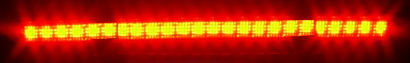
Using the high mounted led brake light as a regen indicator
Regen light
I have had a schematic on the downloads page for over a year that describes using the high mounted led brake light as a MIMA regen indicator. schematic
Several people have asked for more detailed instructions on how and where to connect the relay, so I decided that I should install it on my silver insight, and describe the process. The first thing required was to determine the amount of current that the LED's would require, so I made a direct measurement. The current is only 150MA, and the leds present a nice resistive load, so the relay requirements are very mild. The choice of relays is huge, and many of you will have a relay that would work in your spare component box. I sourced a new relay on Mousers website that is cheap, available, and has a reasonable coil current so the MIMA board does not have to control much power. The Fujitsu MZ-12HG-K-U cost less than $3, and should be easy to work with. The connection location that seems best to me is the blue connector under the passenger side B pillar bezel. The Violet AUX1 wire in the earlier MIMA harness will be extended to reach the B pillar area where the relay will be mounted. On the plug and play harness, just solder a wire to the Aux1 pad on the distribution board, and run it the same way. It can be run under the passenger rug to the wiring area near the passenger door, and then into the B pillar area. The blue 6 pin connector is where we will attach the relay.As you can see from the schematic, we will break the green/white wire that connects to pin 4 of the connector, and put the Normally Closed relay contacts (1-7) between the two ends of this wire. The Normally Open contact(2)will splice into the Blue/yellow connector wire (13.6V) pin 5. Pin 11 of the relay also connects to pin 5. This relay is made for PC mounting, but you can solder the wires directly to the relay pins to make things easier. The final wire is the MIMA AUX wire which connects to pin 12 of the relay. Whenever MIMA detects that more than 15A of regen are happening, it will turn on the LED brake light but not the regular brake lights. To enable MIMA AUX1 for brake light, calibration option 4 needs to be on or not blinking. An added feature may be to have 50% brightness when regen is the activation, and full brightness when the brakes are the activation. Simply add a resistor in series with the wire from the Blue/yellow tap for the 13.6V.I will determine the resistor size that works best when I get my system installed.
(Posted 4/7/2009 by mikey)
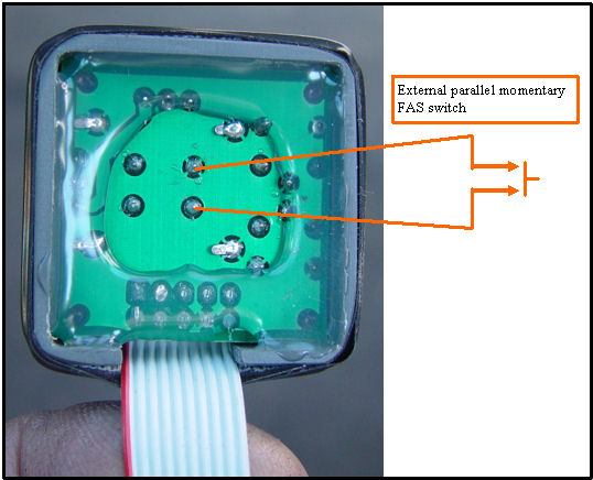
External parallel FAS switch on the joysticks
External FAS switch
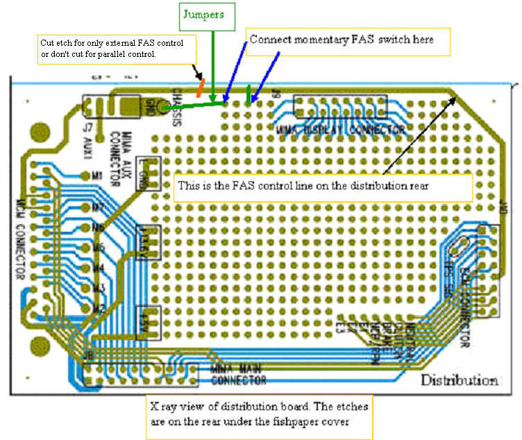
Trying to hold the central joystick switch in the center while pressing and holding the switch down for the 2-5 seconds required for FAS activation can be tricky on a bumpy road. A simple way to add a parallel momentary push button switch to do the FAS activation without disabling the MIMA central switch activation is best accomplished by adding two wires to the joystick central switch and running them to the external momentary switch. Another place to tap into the FAS control line is on the distribution board as shown below. I recommend leaving the MIMA FAS control in place, and putting the external switch in parallel at either the joystick or on the distribution board, as future software may incorporate an option for auto FAS operation.
(Posted 12/30/2008 by mikey)
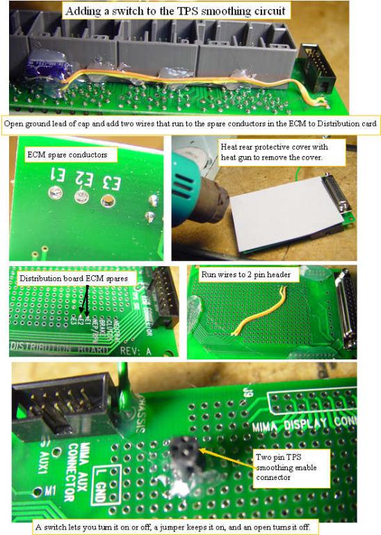
A switch for the TPS smoothing
Making a switch for the TPS smoothing
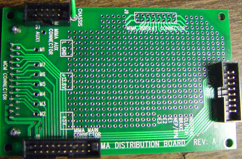
The TPS smoothing creates a very subtle delay in throttle response, that some may want to turn off. Using the extra conductors in the ECM cable and a few short wires, we can add a switch to the TPS smoothing.Again we use the distribution board as the switch connection point.
(Posted 12/20/2008 by mikey)
Dual FAS controls Distribution tie point
Dual FAS controlls
As many MIMA users know, it can be difficult to induce FAS with the MIMA central joystick, on a bumpy road, as you must keep the joystick centered as you press down. A simple additional FAS switch can be connected directly to the distribution board to offer a second method of doing an FAS. Remember this switch must be a momentary switch, as the injectors must operate when an autostart tries to restart the engine. A future software option will offer auto FAS, whenever the shifter is in neutral for 10 seconds, so it is best to do the external switch in parallel. Take the distribution board out of the car, and using a heat gun or hair drier, heat the fish paper backing until the hot melt softens and the fish paper can be removed.The photo is really an Xray view of the card, so the large trace at the top is really on the back side. Using a sharp knife or exacto blade, scrape the green solder mask off the trace. If you want to disable MIMA control of the FAS, cut the trace, if you want parallel push buttons, do not cut. Solder a small 2 pin header for the switch, similar to the MIMA kill switch to the board near the chassis ground, and run two small wires from the trace to one pad, and from the chassis ground to the other.Mount and plug in your switch, and you have an additional FAS control button. The extra switch can also be connected across the joystick central switch as shown above.