Better solution
|
 | |
|
Modified shop light is better solution
|
One of the guys that bought a charger asked if a shop light could be the discharge load, and the answer is yes if it is the right kind.
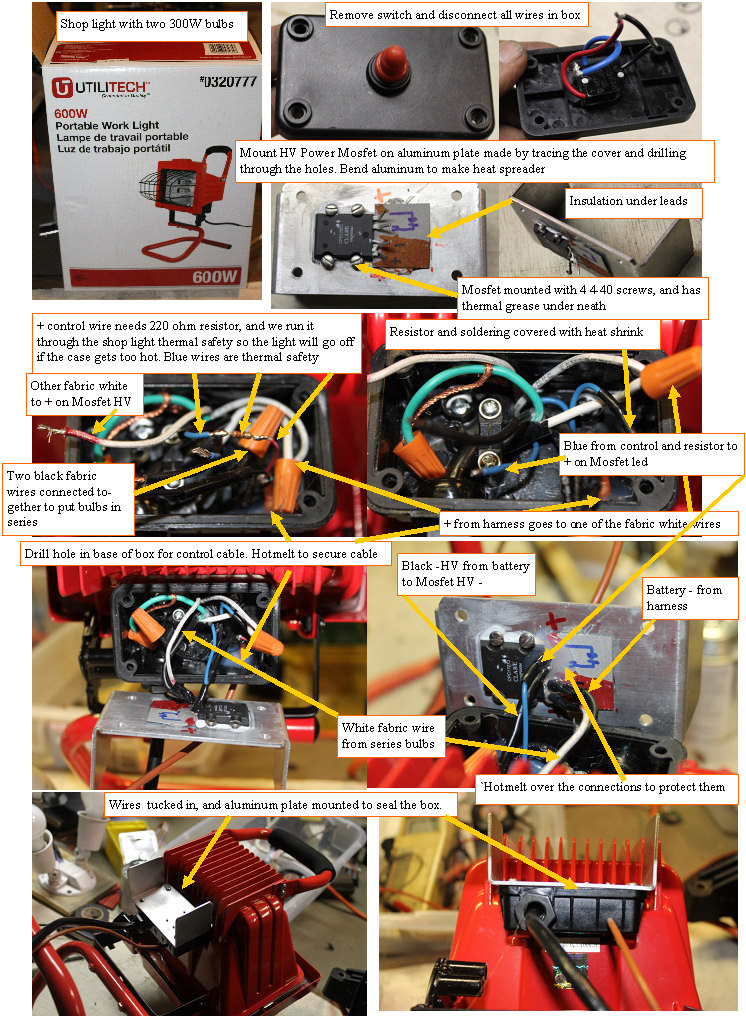
The shop light shown, is sold at Lowes and has two 300W bulbs. I bought one for ~$24, and went to work on it.
First opened the wiring box on the back, and disconnected all of the wires except the green ground wire.
Using an ohmmeter I determined that the white and black high temperature wires connected to the bulbs, and proceeded to connect the two black together to put the bulbs in series.
I removed the pushbutton switch, and used the black cover to mark the outline and hole positions in an 1/8" thick aluminum plate.
Drilled 4 holes to mate up with the power mosfet mounting surfaces, and the 4 mounting holes. Cut a notch out of the top two edges of the plate so it would clear the lights back heat sink.
Bent the two tabs out to help any heat generated to better dissipate. Drilled a small hole for the control cable under the box, and after putting a small zip tie on the cable, aI hotmelted the cable inside the box to stop and rotation or motion.
The white(+HV) from the harness was connected to one end of the series bulbs, and the other was connected to the + lead of the mosfet HV side.
The black (-HV) from the harness goes to the - lead of the MOSFET HV side.
The control cable Black wire goes directly to the MOSFET Opto input - lead, and the red control wire goes through a 180 ohm resistor, and through the blue wires of the shop light thermal cutout switch. The other blue wire goes to the + opto input of the MOSFET. The Mosfet lead area has a small piece of fish paper insulation, and after soldering the whole terminal side of the MOSFET is covered to protect the leads and connections, The aluminum cover with MOSFET is mounted on the box.
Wire the AUX connector to the control wires, and you are good to go once the adapter harness is attached.
A video of this modification
|
|