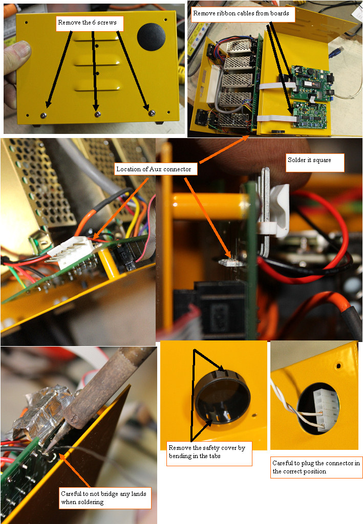
Adding the Aux connector
|
 | |
|
Installing the AUX connector
|
Ok, I am a dummy for not putting the connector in the board, but when I was building these chargers, I did not see the dis charger as a use for the port, and was only seeing it as a way to increase the voltage for 300V+ packs, and out of the 100 chargers, no one wanted that, so I decided to leave it off.
OK, My bad, but now how do we get it done.
The connector is able to be soldered to the board without removing all the power supplies and interconnect boards if you are careful.The first pin will set the angle that the connector is mounted at, so be careful to hold it square when completing the first solder joint.
Be sure to carefully inspect the connections to assure that no solder bridges have occurred between adjacent pins or traces.
Anyone that is uncomfortable with soldering this, can send the charger in a well packed flat rate box, and include $28 for the return shipping,and $25 for the upgrade kit (larger microcontroller with latest code, and the new port cover) and I will install the connector and microcontroller and get the charger ready to go with new software and calibration for you and send it back.
|
|