|
Installing the resistor
|
 | |
|
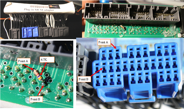
Adding the pull up resistor
|
The MCM plug in adapter board in the rear of the car is where we will do the modification.
Start by uncovering the pc board just below the big grey connector.
Removing the label can be easy or hard, depending on how well the hot glue fused to the fishpaper and board. I have found that the fishPaper will unstick if you wiggle and work it loose, and the hotglue on the PC board can also be lifted off the board in most cases. A heat gun is a messier way to gain access, but can be used as a last resort.
The exact position of the two connection points can best be seen in the photo of the PC board artwork at the top of this blog.
The resistor can be any 4.7K 1/8 to 1/4 W resistor.
Bend the leads at a right angle, and tin the cut off leads.
The attachment points will also want to be freshly tinned.
Finally solder the resistor to the two points, being observant that you do not bridge the two close traces to the top resistor tie point.
After a close visual inspection, stabilize the resistor with a dab of hot glue, and also fold the fish paper cover back over the board and resistor, and plug it back into the car, and your IMA problems should go away.
|
|
|
