|
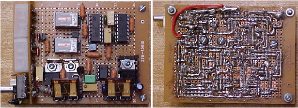
JoeCVT main boardAs a forum member at insightcentral.net, I was very interested in the MIMA project from the very beginning when Mike and Yves first tapped into the wiring harness and discovered manual control of the IMA. Shortly afterwards, Mike designed a circuit (MIMA_L) and made it available to the public with all of the parts needed to build your own MIMA. I do not have the electronics background to design a circuit like this but I did want to try to build my own MIMA. I ordered all of the same parts that Mike had in his circuit and while waiting for them to come in, I created diagrams of how I would layout the parts on the board. I wanted to make the smallest board possible and solder traces onto a small plain board that I got from Radio Shack. My soldering skills are not so impressive but here is what the front and back of the board looks like:
|
 | |
|
Joecvt MIMA L board
|
|
|
|
