Installing the Genesis One Universal grid charger in an Insight
To make this harness install as clear, sure and safe as possible, there will be not only web based instructions, but also a video going through the whole process in a lot of detail. This page is the draft of the instructions for installing the harness,and will grow into the final web based install instructions as the systems begine to be installed. For now, it is simply a way for people to see how things are shaping up, and give the technical guys something to critique, so we may make this install as painless and sure as possible.
Insight harness
harness and optonal extension harness
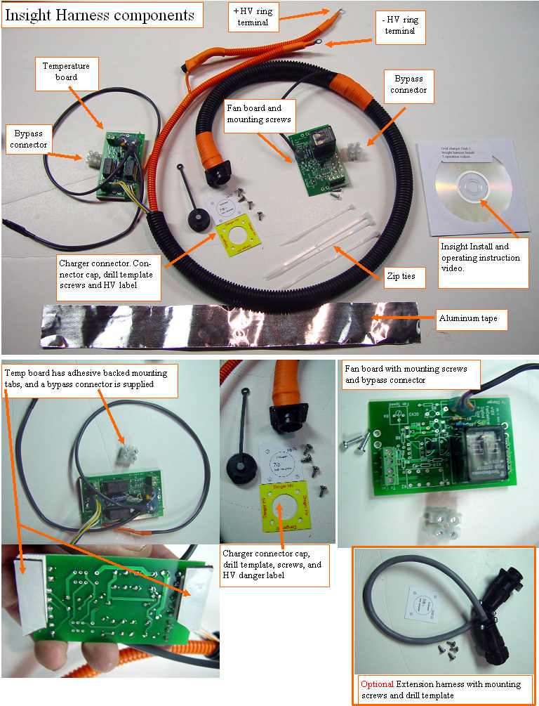
Here is a photo of what you get with an Insight harness.
Disassembly of the IMA box Preparation:
The following tools and equipment will be needed to complete this installation:
Good pair of small wire cutters Wire stripper Roll of black electrical tape Metric wrenches #2 Phillip screwdriver Wide flat blade screwdriver Torque driver #T30 Digital multimeter, even a cheapo $10 radio shack one will be good enough.
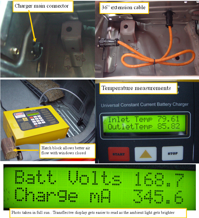
Mounting the charger connector
bulkhead install
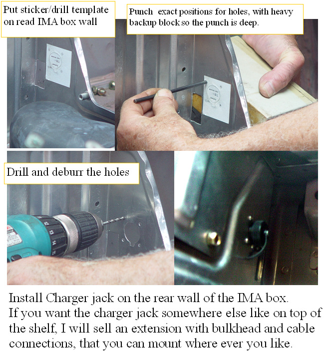
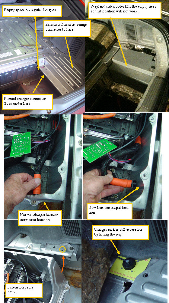
The charger main connector will be mounted to the rear of the IMA box. Mount the stick on drill template to the IMA box at the desired location, Have someone press against the opposite side of the box with a heavy backup block so the punches are deep and distinct. Drill the 4 screw holes, then the center where the 7/8 hole will be. Enlarge the center hole to 7/8" with the step drill, deburr and you are ready to mount bulkhead connector. If a more accessible connector is desired, extension cables will be available, that will allow a duplicate bulkhead connector to be installed on the top of the small shelf as shown in the next photos.
Temperature board
Temp board connections
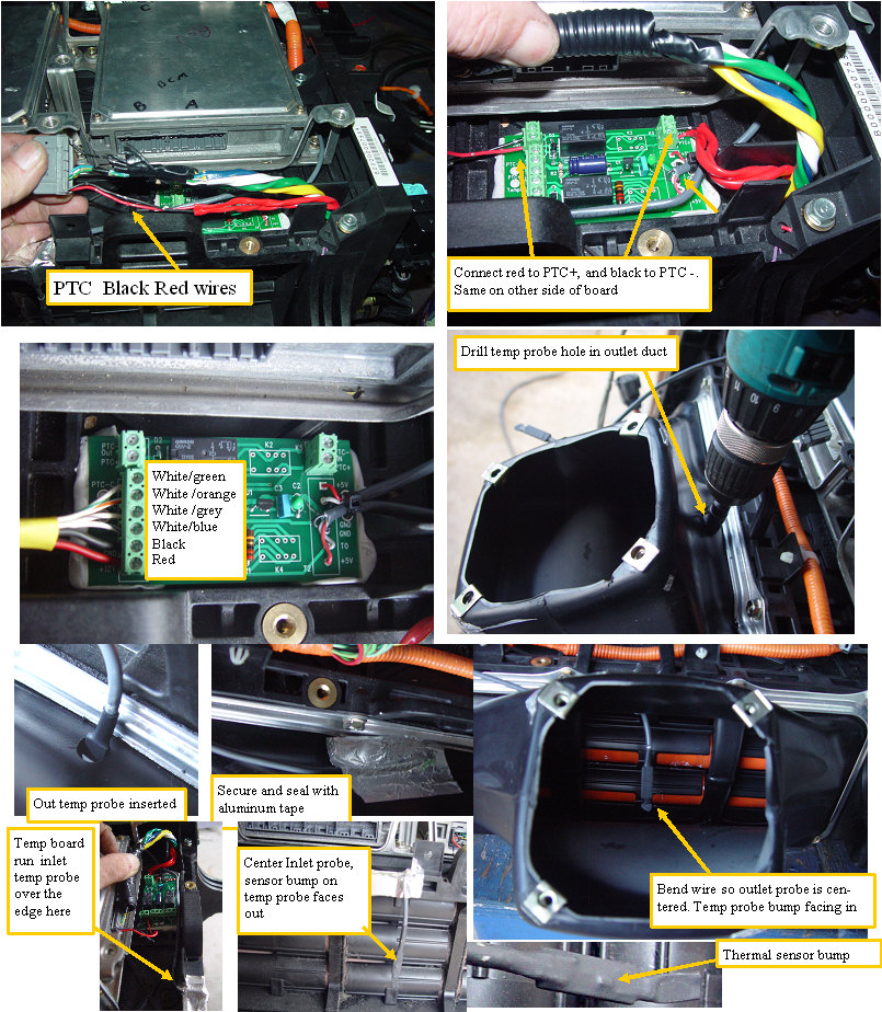
The temp board is mounted just to the rear of the BCM so the PTC wires can be tapped. The harness picks up the PTC, inlet and outlet pack temperatures at this point.
Mounting the temp and the Fan boards
Mounting the fan and temp boards
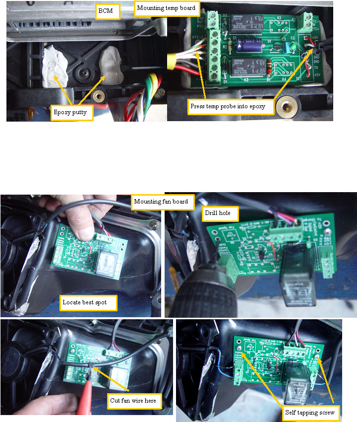
The fan board is screwed right on the side of the fan shroud. This board allows the charger to turn the fan on and off as required.
The pack is cleaned in the mounting area, so the epoxy sticks strongly. The temp board is first coated with spray wax, then pressed down into the soft epoxy putty. Waxed screws are threaded into the epoxy through the board mounting holes. When the epoxy is set, the board and screws can be removed from their form fit mounting pads.
First full install in my red Insight
First full install and charge
Made a 36" extension cable, which will only need to be ~12" if the shelf is where you want to mount the charger jack. I may try mounting the jack on my rear bumper, so I wanted a long cable. LCD is very easy to read in full sunlight, it is a transflective type which has a reflective backing so ambient light only makes it easier to read.
Sub woofer in charger output area
Subwoofer in the way
Just when you think you have all the details worked out, another pops up. One of the charger customers, has a Wayland subwoofer in the small empty area where we were planing to run the charger connector. After a look at the layout, it looks like simply drilling the outlet hole on the side rather than the back of the IMA box, and using the extension harness to move the connection tothe deck top just in front of the shelf will work just fine. It is a bit more work to drill and debur the holes, and screw in the mounting screws, but not by much. it will be necessary to pull out the sub woofer to get access to the required area. Should be able to just lift the rug to connect the charger, and the sub woofer should go right back where it was.