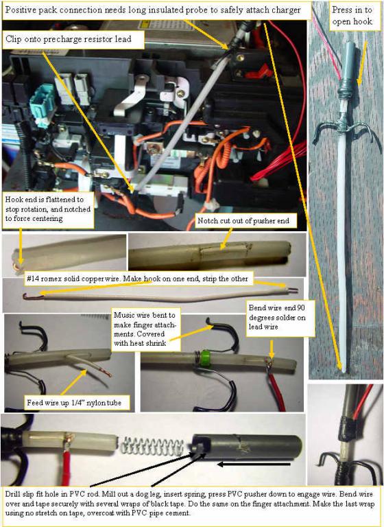
Building the HV probe for the + attachment
|
 | |
|
How to safely tap onto the battery pack + terminal
|
If you looked at your car and said how can I connect to that bottom point where the battery pack positive input resides without shorting something out, or getting killed by the HV, here is how I did it.
I looked on line to buy long clip on test probes, and did not like the selection or price, so I rummaged in my stuff pile, and came out with a piece of 1/4" OD nylon tubing, a piece of #14 romex, a 1/2" PVC rod, and a compression spring.
I cut the nylon tube to the length of the required probe. I squeezed one end in a vice after inserting a 1/8 " rectangular spacer. This cold formed the tube so it was rectangular. I stripped the #14 wire, and formed a tight hook in the end.I cut a V in the long side of the nylon rectangle, to lock the probe onto the resistor lead.
About 1" from the other end of the tubing I used an exacto blade to cut out a rectangle that was the same width as the wire was thick, so the wire slides in the slot.
I fed the wire up through the tube and when it came out the slot, I pulled the hook into the full retracted position, and at the top of the slot, I made a 90 degree bend in the wire, stripped the end, and soldered on my red + wire.
I put the PVC rod in a vice and drilled a .266" hole in the end to a depth that would just start to compress the spring when the assembly was put together. I used my milling machine to make a dog leg in the PVC rod, so the wire would lock into the dog leg. You should be able to carve the dogleg with an exacto knife, just don't cut your self.
The spring is dropped in the PVC rod and the assembly is pushed together compressing the spring then engaging the wire in the dog leg.
Once the operation is tested by pressing the PVC towards the nylon tube, a piece of music wire was bent and wound to a shape like a hypodermic needle finger hook. A wire tie was tightened on the nylon tube just below the fully compressed PVC pushers fully extended position. The finger hooks are covered with a small diameter heat shrink and the tightly taped in position with black tape.Wrap 4 or five wraps tightly, then one without stretching. Bend the wire over the PVC pusher, then tape the same way, 4-5 tight wraps, one no tension. Then using PVC pipe cement coat both tape jobs with a thin even layer. This will bond the black tape together so it will never get sticky or loosen up.
One custom HV spring loaded attachment probe.
|
|
