With the many projects I hope to work on, some extra hands are always welcome. Check here to see if their will be a workshop if you want to come up and lend a hand. Present project: Design, build, and test an IMA-EV mod to give full electric mode to the gen 1 Insight
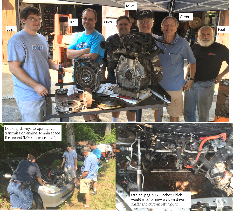
IMA-EV mod workshop 1 discussing the options
IMA EV workshop 1 the team
The options discussed for the mod covered a of of things so I will try to filter it down based on the final consensus A stub axle firmly attached to the motor output flange would be the best place to start, so we will make the shaft as soon as a bearing is selected. the IMA rotor will be bored through to eliminate the bolt attachment rear surface. Bearings that can stand a 400 lb side load (clutch) and allow maximum free space will be sourced to fit inside the IMA rotor. Once this is made we will test it on the engine I have on the bench, or the Insight on a test stand.
A scaled drawing of all the components will be made including the bearings.
The pin clutch is still the best plan although we have no idea what that will look like until we see how much space we have to work in.
Some concepts to consider Smart EV clutch: This would not allow the EV clutch to activate or deactivate unless the IMA is stopped and the engine is stopped (clutch in engine stopped) Concept: A magnet or several magnets would be inserted in the stub axle. A coil on the rotating rotor would generate pulses whenever the rotor and the stub axle/engine were not linked, as in the EV mode. Pulses would be rectified and would charge a supercap for energy storage to generate a regulated DC supply within the IMA rotor clutch assembly. A surface mount PIC micro would be the smart clutch processor. The pulses would also tell the micro if the stub axle is turning at a different speed than the rotor (pulses). an optical or serial signal would be need to communicate to the smart clutch the users intention. Not clear as to the best way to accomplish that communication.
The clutch pin actuator (small gear motor or solenoid), would push the spring loaded pin / pins toward the clutch plate and the IMA motor would be rotated slowly until the pins engaged. The main clutch is out so IMA would be commanded to rotate slowly until the pins were engaged in the stopped engine side of the clutch.An engaged/disengaged control signal would be sent out from the clutch to confirm it is ok to start the engine.
Going in to EV mode on the fly.
Main clutch in, fas to engine off, send EV disengage command. When flywheel stops (dynamic breaking with IMA motor)and shows no relative rotation to the stopped engine the smart EV clutch would pull the pins out and confirm it is disengaged and you would drive in EV mode which could allow MIMA or possibally the TPS signal (throttle pedal)to control the IMA motor in the EV mode.
Starting the car: Main clutch in, engage command sent, EV pins out, rotate IMA slowly until springs engage. send engaged signal, start engine normally with IMA.
going from EV to driven on the fly: main clutch in,send engage signal,wait for stop, pins out,slow rotate, engage complete start engine or pop clutch to restart.
If this don't work plan B: Second IMA motor driving one or both of the rear wheels with timing belt drive. several ways to make it happen no plans yet.
Ima motor and transmission would not be mechanically modified, but the three proximity position sensor signals and the 3 phase drive signals would be switched to the second IMA motor and the car put in neutral engine off. Drive via MIMA like control or switch scaled TPS signal. that it for today
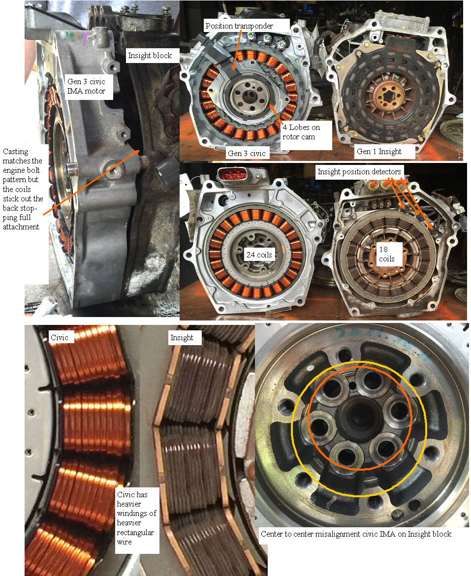
IMA-EV mod workshop 1 gen 3 civic to gen 1 Insight IMA differences
gen 3 Civiv to gen 1 Insight IMA motor comparison
Had a fruitful day discussing the pros and cons of various ways to make the IMA motor separate from the engine for a true eV mode. Also got top compare a gen 3 civic IMA motor with an Insight which was very interesting. The two types of IMA motor aluminum castings were virtually the same bolt patterns. The civic is a bit thinner in the casting thickness but a lot of extra depth beyond the casting is filled with the deeper coils so it was not possible to mat it with the Insight block there is also a different center point of the rotor which would be the biggest obstacle to overcome. The civic has a position transducer similar to the Prius instead of the 3 proximity sensors used in the Insight for position feedback. close but no cigar.
IMA-EV mod
2016 Hybrid festival at Geralds place was a great gathering. The highlight for me was to see that Mudder was so far along on his Linsight project and the end was in sight. For me this is a dream come true, big batteries means MIMA is not limited any longer after all those MPG runs where you just needed a bit moor juice to hole on to that 110 MPG in theory one could have 75 Ah of batteries The best partis that he has totally hacked the BMS and MCM and is replacing them with Linsight that alone removed a lot of the mystery as to how that part of the system was controlled. What was the other dream from day one, Pure EV mode. That is what we will devote at least 2 Saturday workshops weather permitting per month until we get this done. First meeting is Sept 10 9-10AM may run all afternoon.?
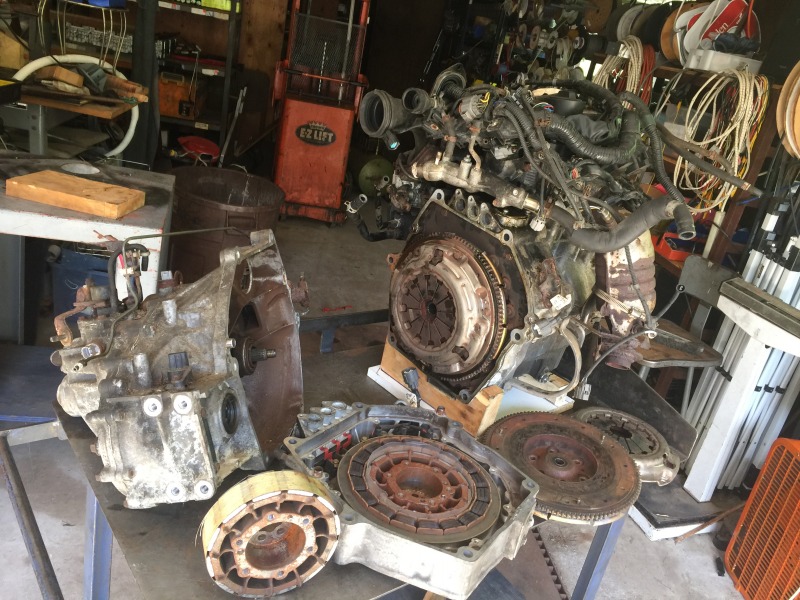
Have a good Insight engine IMA motor, a 5 speed, some rotors,flywheels to measure look at the options.
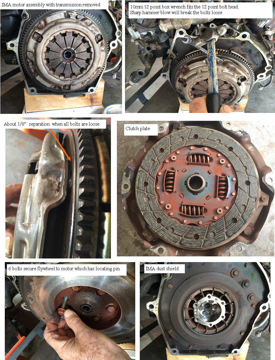
disassembly of clutch and flywheel from IMA motor
clutch and flywheel removal
got the clutch and flywheel removed from the IMA motor. As well as measuring the force required to press the clutch throw out springs fully. I put the clutch spring assembly on bathroom scale while pressing in the spring with my drill press. Took ~370 lbs to fully disengage the clutch. This will be an end load on the rotor bearings.
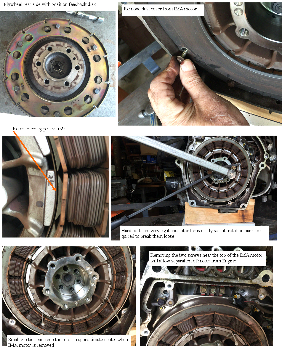
removing the (IMA motor
removing the IMA motor
Next we need to remove the IMA dust cover and the central bolts. The bolts are very tight so an anti rotation bar can be set up to prevent the rotor from turning until all the bolts are loosened.
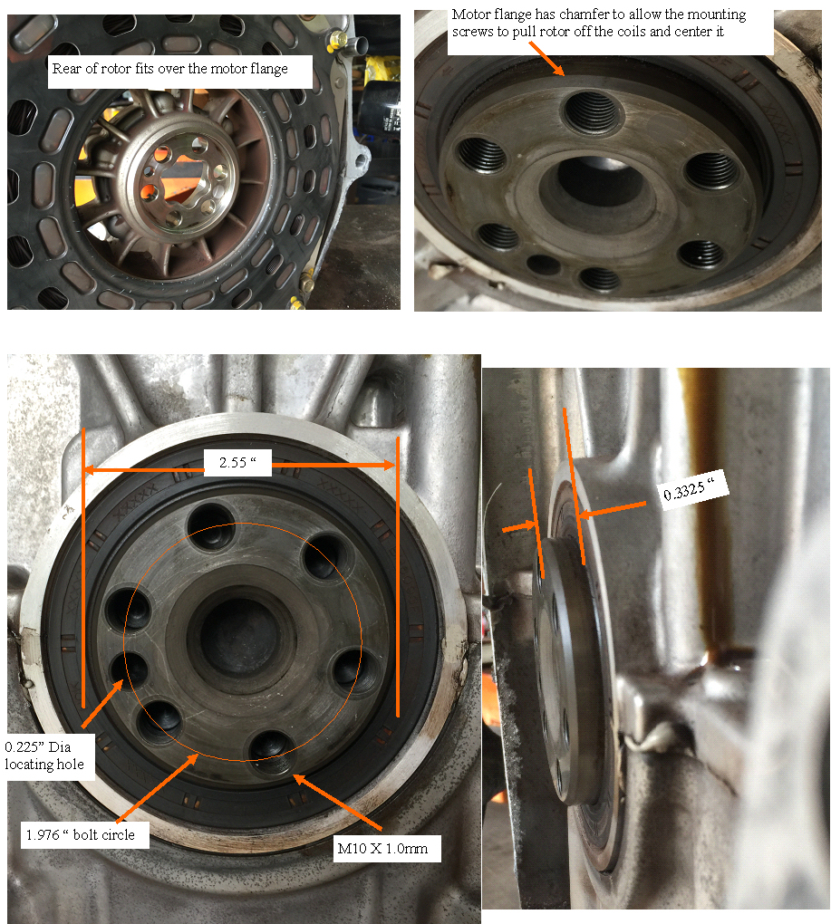
engine to rotor interface
mounting surfaces
A close look at the rear of the rotor and the Engine output flange
14 year old cars have rust issues
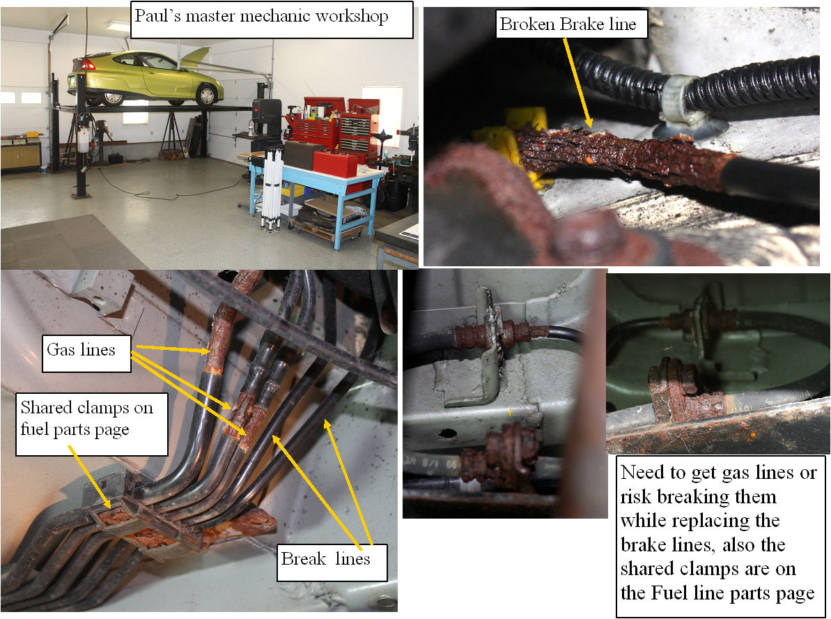
Making the Insight safe again
My 3 Insights are all 14 years old, and after having the breaks and gas lines fail on 2 of the cars, I am looking at the items that any Insight owner will need to deal with to keep the car safe, and running as long as possible. Will start with the serious gas and brake line rust issues. I got a set of lines and parts from Majestic Honda, and luckily They are only 35 miles from here, so I could drive out and get the long crazy break lines. One gas like is too big to ship so their parts list does not show it, but it can be included with the order if you get the part nymber from their sales guy. I should have got under the car and removed the covers, as it became obvious that one should always replace both the brake and gas lines as they share many of the same clamps, and both would make a very bad day for you if they failed while you were on the road.Ordered the gas lines and clamps and will wait to start the project until all the parts are in hand. Also very lucky to have a buddy just a few miles from here that has a great workshop with overhead car lift. Would hate to try this in my pit or on jack stands.
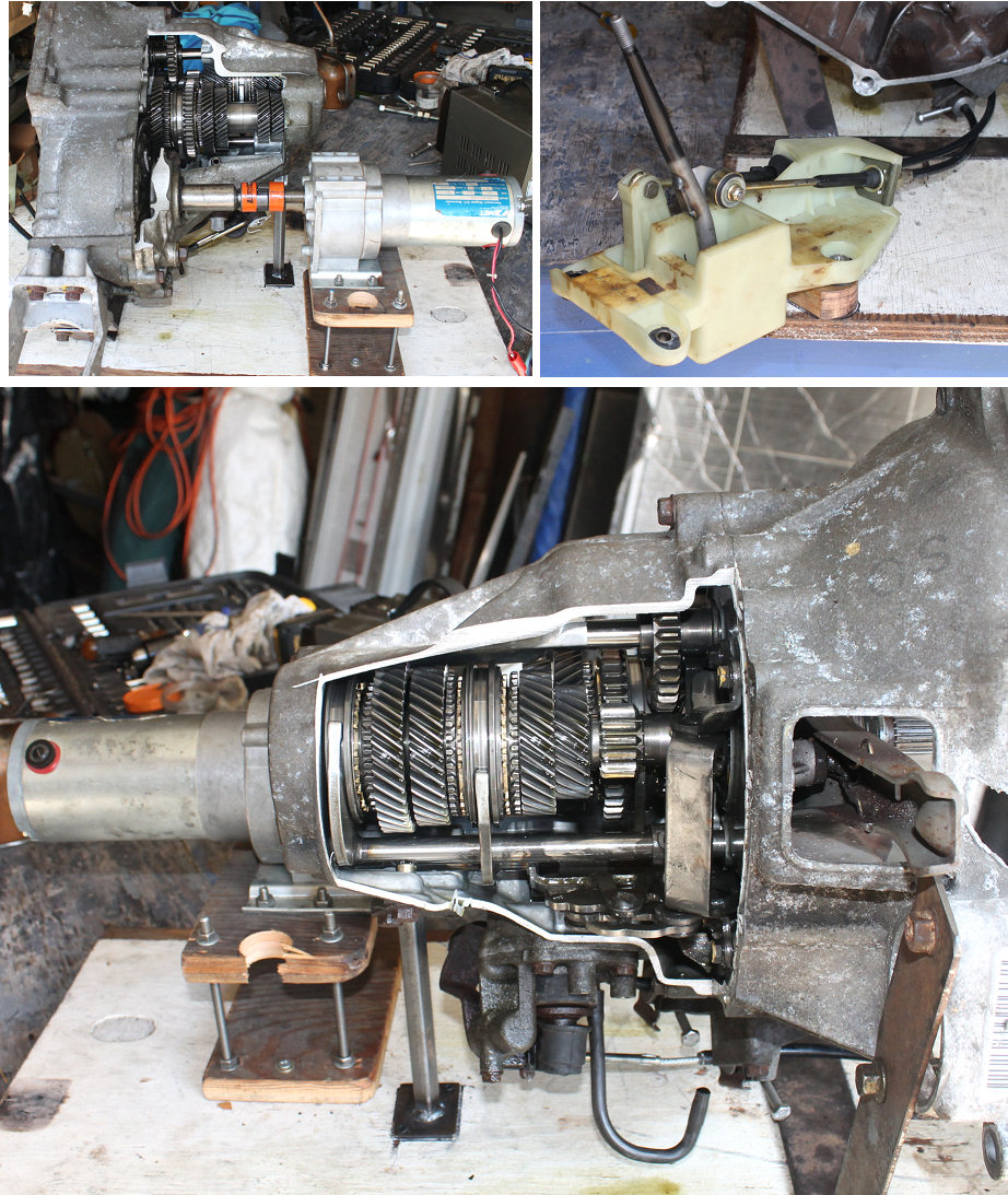
The transmission is operational
The transmision is running
Spent a bit of time finishing up the cutaway transmission. Remounted the transmission so the cutaway was up, mounted a gearmotor to the output end of the transmission so I can simulate a shift with clutch in. The hardest part was getting the shifter to work, but after some hacking, I have it operating like new. The next step will be to carefully document the operation of the transmission as it goes through the gears in both directions. Since this is a transmission, a video will be a better way to explore how it works. Sat workshop Sep 14 (tomorrow) will be when we get into it again.Can clearly see everything going on, so it should be very informative.
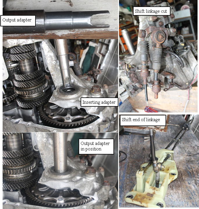
getting the shift linkage and output shaft made
output shaft and shift linkage
I dug the shifter out of the green parts car, and made an output shaft that bypasses the differential, so I can drive the output with a motor as though the car was coasting with the clutch in. Will tinker with the project during the week, and try to finish it by friday.
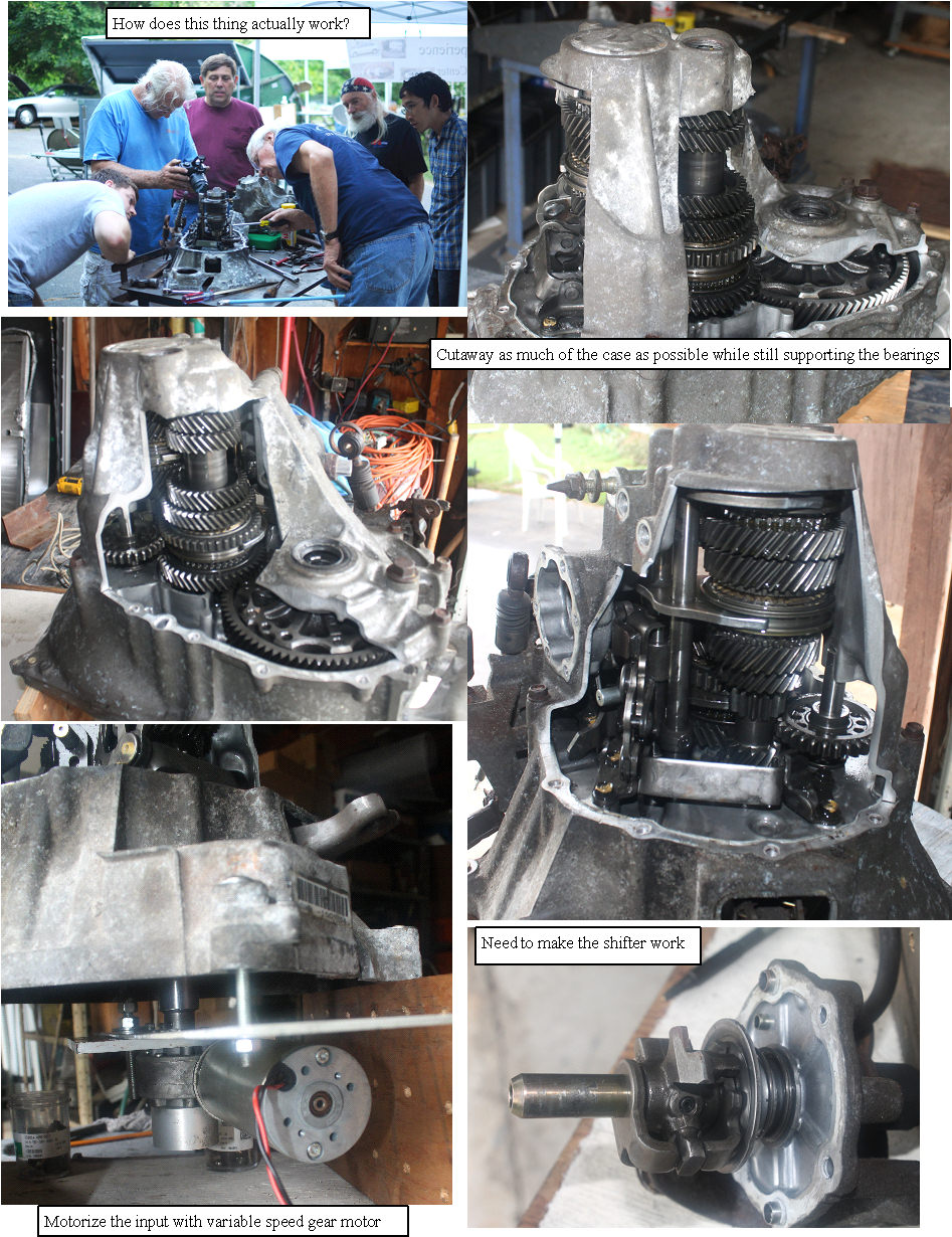
workshops 2013 Figuring out the 5 speed transmission
a better look at the working 5 speed transmission
My green and red Insight are both suffering from the 3-2 downshift issues, and after reading about syncro rings and clocking tabs,and other proposed issues with the 5 speed transmission, I decided it was time to better understand how the 5 speed actually works, and since I had the tranny from the green insight with a broken bell housing, why not make a visible working tranny and see what can be learned. While many people have fixed the downshift problem, and they understand how the transmissions works better than I,so I want to really understand it, and hopefully document it in an easy to understand and visually demonstrated way. This will be a part time project, and will be something we can work on in the new series of Saturday workshops I will start this week.
New Saturday workshop helper
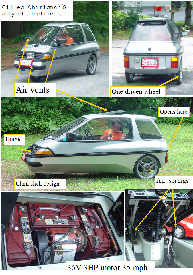
City EL EV
Gilles and I met at Altwheels festival in Boston two years ago. He recently got himself a City EL electric vehicle and finally got through all the red tape to put it on the road in Massachusetts.He lives only about 15 miles away, so he hauled his EV over for today's Saturday workshop. We took it for a few spins up and down the road, measured the current draw (90A max). Not much power, since it is basically a 36V golf cart with a sealed cabin. We discussed the options for giving it a bit more pep. A nice day with a new toy to check out, and a mechanical engineer joins the Saturday crew.
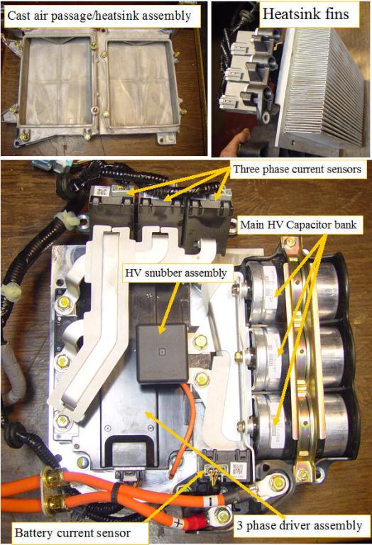
Civic power electronics
Civic power electronics
Ron from Hybrid battery repair gave me some civic power electronics that came with some of the civic battery packs he bought. I disassembled one to get a better look at the parts. Shown here is the major components.
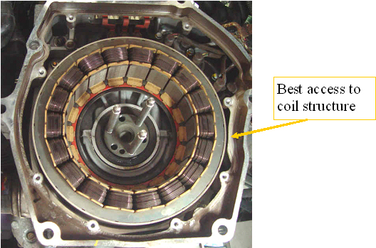
IMA motor temp
IMA temp
With MIMA a lot of assist can be sent to the IMA motor, but we have no way to know if it is getting too hot. A thermal probe could be attached to the magnet structure by drilling a small hole in the side case right where the case is in the closest proximity to the coil structure.
WORKSHOP 2008
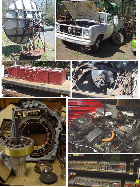
Some of the fun projects for this year
Time to get some help on the many projects underway. EV bucket truck battery mount wiring and test, new solar tracker drive system, inventory damage to green machine and begin repair/removal of engine and IMA, build 48V prius subpack with pressure switch for charge termination,Ev ATV, cycle old 6V batteries for use on EV bucket truck.Finish the test point breakout panels on the Insight on a stand, make Insight IMA electric motor stand alone with bearings and end plates. Thats just the start. Have fun, and learn about how this stuff works, and help me with my green projects.
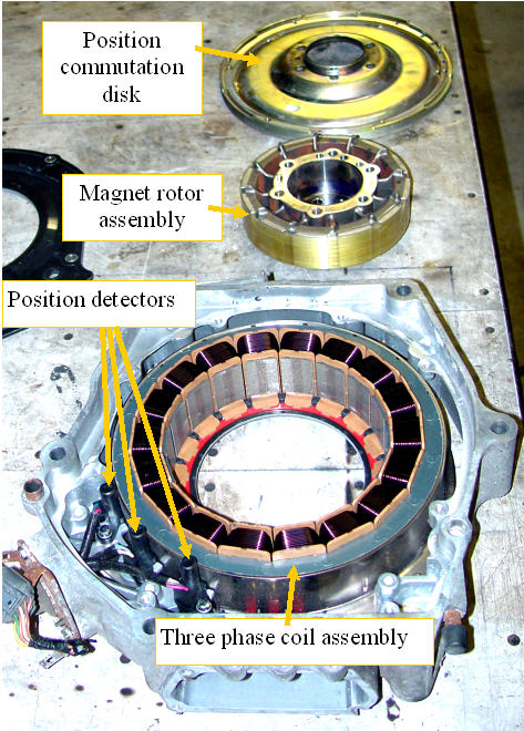
IMA motor is added to my inventory
IMA motor
I finally have a complete IMA motor that is not in a working car that I can play with. I will need to build a central output shaft with bearings, for the magnet assembly to get to the point where it is a usable motor. Unfortunately the guy wanted to keep the power electronics for use with another motor. If anyone has an Insight power electronics package sitting in their basement or garage, that they would like to see put to good use please contact me. Once I turn this into a functioning motor, there are several uses that I have in mind: 1)Three phase motor demo for the hybrid training class. 2)We would need to make the demo do more than turn, so mounting it on an electric ATV or go cart may be fun. 3)driving a rear wheel on an Insight for a pure EV mode,possibly by electrically switching the IMA drive signals to the EV motor and back to swap modes? 4) explore using the motor as a generator. Some specs not easily available. The complete motor with rotor weighs about 43 lbs. The 3 phase winding assembly weighs 21.9 lbs The rotor 8.9 The aluminum casting with sensors 6 The steel commutator disk 6 The thick and heavy commutator disk is may also also play a part of the magnetic path, or shielding
Cutting deeper
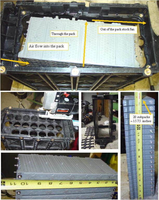
I cut the remaining inner webs from the battery case, and tried 20 prius subpacks. It fit nicely, and if mounted as shown, the existing battery fan should keep them cool.
Thoughts on my ideal Insight pack
The ideal battery pack?
Why a different battery pack? First reason,the present packs are not holding up. We can't change the control software that is not doing a good battery management job.We need a replacement pack that fits where the stock pack is, uses the same power/relay board and fuse, uses prius subpacks, with the battery management software built into the new pack (open source).This pack would interface with the present BCM, and simulate the battery signals, so the stock SOC guage would work normally to show the battery SOC, and the BCM always thinks the pack is perfect.Any error that our battery management system would detect can shout down the IMA by simulating an error to the stock BCM, which will respond by setting an IMA light and disabling the system.
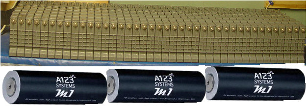
With PIMA, the bigger the pack, the longer you can run in Electric Priority mode, and the longer you can get >100mpg. What is the ultimate Insight pack for the minimum cost? Of course a pack of the new A123 LiPo Hybrid batteries would be my first choice. But my finances dictate that unless they donate some to the cause, I will have to go with NIMH. I have almost enough Prius subpacks to make up four 144V strings of 20 prius batteries. The 4 packs could replace the present battery pack, with three additional parallel booster packs, increasing the total pack AH to 26. The 80% to 20% SOC range would now have 16AH instead of 4AH. I estimate that this setup will extend the Boosted Battery PIMA range (> 100 mpg) to well over 60 miles, even at 65mph and hills. With proper design,each of the 4 packs could also work individually as a plug in replacement for the stock Insight pack, or as part of a multy pack system. Will probably need some custom rear springs to maintain proper ride height. Then we build a BLDC 10hp 144V electric rear drive system and power it from the same battery pack.Allowing an electric only mode with possibly 40 mile range, but with the ability to recharge with gas while driving under full electric. Lots of possibilities, the only missing ingredient is the money to get the components and a good mixed signal storage oscilloscope, so I can proceed efficiently. Too many projects not enough time or money .
Prius subpacks in an Insight
Hacking the spare Insight battery case
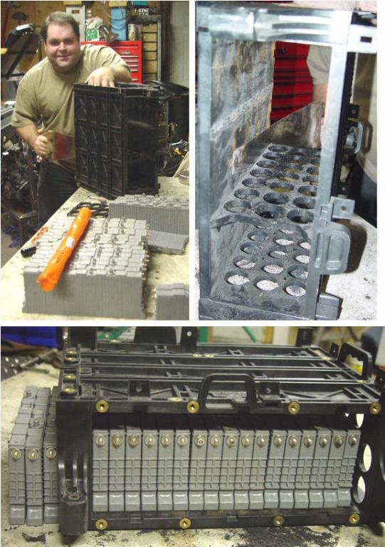
Will Chabotte came up for the Jan 19 workshop, and we got into hacking the ribs out of the spare Insight battery case. A sharp carpenters saw did a nice job cutting the plastic, but only after we put in a good deal of elbow grease. If the side ribs are also removed, we can get 20 subpacks into the Insight case. It is a toss up as to whether this is the best route to go, as the sawing and modifications are time consuming,and we still have to deal with cooling the subpacks properly, and making all the connections, but in theory it can be made to work. A custom case with the cooling and subpack clamping considered in the design will make a better functioning solution, but the case would need to be built from scratch. It's never easy.
Other projects
some of the projects we will be working on
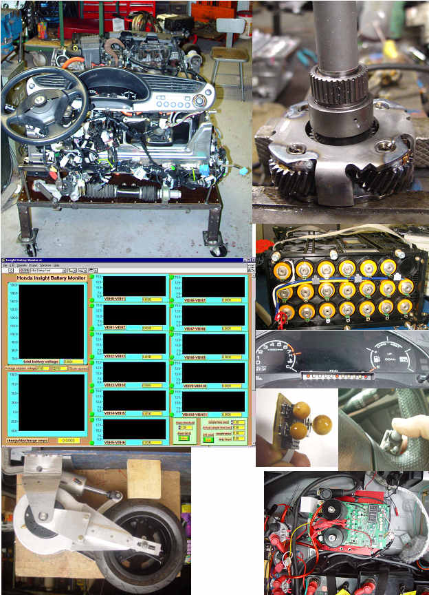
Other projects that are in the works, not necessarily in any order. 1. Insight on a stand: Get ICE to run continuously. Add output axles and wheel spindles so Motor generators can be attached.(full hybrid dyno functionality) Add the transmission lift system powered by the EPS unit. Test IMA system operation with dyno.
2.Develop Prius inverter driver to power the modified synergy MG set for potential EV use.
3.Develop Insight Battery test system that will look at individual subpack voltages on all 20 subpacks, four temp sensors, current in and out of pack, SOC and capacity test.
4. Develop replacement for the Insight battery that has higher capacity cells, and lithium chemistry.
5. Mounting of EV modified Prius synergy drive in a stripped down Insight, with full conversion to EV as the final goal.
6. V-boost integration into Insight system, and control tie in with MIMA.
7. Development of MIMA based MPG maximizing cruise control that will control throttle as well as IMA.
8. MIMA LCD display, and steering wheel mounted Joystick
9.High speed E-wheel
10. Bolt on E-wheel drive system for one of the existing Insight rear wheels.
11. convert telephone truck to full electric.
12. build data acquisition system for Insight battery pack.
13. Determine best way to add solar pack charger.
14. Put bearings and output shaft on the Insight IMA motor.
15. Determine best adhesion system for direct solar cell application to the roof and hood.
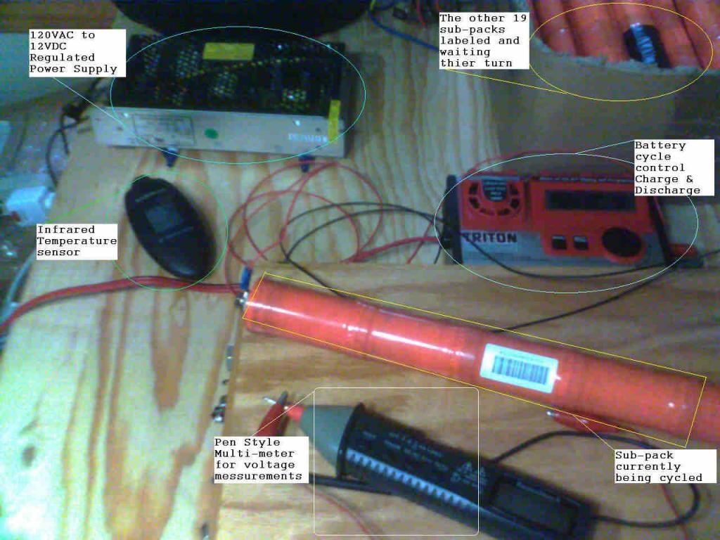
Early results of subpack testing
Ian's test setup
Ian has ran each subpack through at least one cycle of charge/discharge to determine AH, effect of cycling, and potential cell imbalances. Here is the firs look at the data.
#1> Determine the Capacity of the sub-packs #2> Determine effect of cycling sub-packs #3> Compare cell resistances in sub-packs
Cell resistance variation can be seen in the difference in temperatures. Must make sure to take into account the how batteries charge as a sub-pack. Each cells resistance is in series Cells in series all have the same current but not the same voltage. The heat / resistance can also be cause by cells that are lower capacity reaching full capacity sooner. Once a NiMH battery reaches its SOC Capacity any further charging will see a temperature increase. This is a variable resistance based on battery SOC. Faster / higher current charges and discharges will more show the resistance of the battery / sub-packs Slower / lower current charges and discharges will more show the true capacity of the battery and more fully cycle it.
4 subpacks started with 0000 mAh of initial SOC 6 subpacks started with over 2,000 mAh of initial SOC
9 subpacks initially took ~6,000+ mAh of charge 4 subpacks initially took less than 3,000 mAh of charge
Fast / High Current Cycles Discharge at 3.0 Amps Charge at 5.0 Amps Set for NiMH 6 cell pack 6,000 mah expected 7,000 mah limit Discharge to 0.9 V per cell x 6 cells = 5.4 V per Sub Pack There is a 15 minute delay between discharge and charge * = Ian Aborted charge due to temp reading
Slow / low current Cycles Discharge at 1.0 Amps Charge at 1.0 Amps Set for NiMH 6 cell pack 6,000 mah expected 7,000 mah limit Discharge to 0.9 V per cell x 6 cells = 5.4 V per Sub Pack There is a 15 minute delay between discharge and charge Slow / low current does not seem to be producing temp variation in cells of sub-pack
Subpack Cycle Date Action Vi mAh Degrees F + Left to - Right
Obviously the pack was badly unbalanced. The interesting thing here was that the pack was working relatively normally and had no IMA code in the silver Insight that it came from.I did have problems trying to start the car after it sat for some time. Ian Cycled each subpack and found that they all seemed to respond with nearly full AH in subsequent cycles.
Silver pack reassembled.
some interesting observations
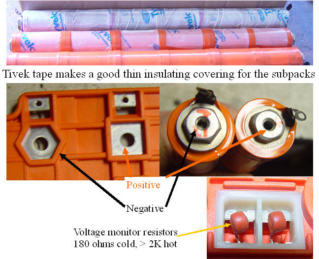
After Ian's thorough cycling experiment, we reassembled the pack. While the pack was apart, we did a few more interesting test. 1. The positive temp coefficient band that passes through the side of each 6 cell subpack was removed in order to get some data about it's temperature response. Each 6 cell strip measures 1.5 ohm when at room temp. It raises to 2 ohms at about 135F, and is 4 ohms @ 160F.
2. The 180 ohm "resistors" that are in each of the 10 monitor lines feeding to the BCM, are also positive temp coefficient devices. They act like self resettable thermal fuses, as their resistance goes into the K ohm range when they get hot, and returns to 180 ohms when cool.
3. The battery end studs are either a square (+), or a hex (-), and the orange connection plate has mating sockets, so it is virtually impossible to assemble the pack wrong.
When the pack was assembled, we dropped it back into the silver insight. The car had been having trouble cranking just before the pack was removed, but the recharged and cycled pack turned over the car and it started immediately,just as it should, even though the 12V battery had been out of the car for 2 weeks prior, so the computers were all reset, and the SOC showed zero. This means that the car must do a HV pack voltage check before it decides to use it for cranking,even though it did not know the SOC. Once we saw the easy start, and no codes, we pulled Ian's pack, and after mounting his BCM and MCM on the silver cars pack, we installed it in his car, so he can watch it on his 500 mile/week commute. He will also test and cycle his subpacks, by exposing the two ends of the strings,to see how well balanced it is. We suspect that a pack must sit for a day or so to have the voltage settle to it's no load voltage,and show any imbalance? I also welded up a radiator mount for the Insight on a stand, and hope to get it running this week. Another fruitful Sat. Graphs of the battery pack initial conditions, as well as Ians pack initial conditions: Ian's Graphs