PCD is fixed and ready to go
|
 | |
|
Ready to drop into some buggy
|
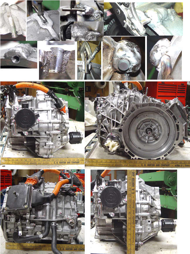
I broke out the Tig welder again, and fixed both sides of the broken case. I started by finding a piece of steel rod that was just a bit smaller in diameter than the 8mm X 1.25mm tap drill. I built up aluminum over the steel rod, then removed the rod with vice grips. I drilled out the hole with the correct tap drill, then rethreaded the hole with the 8mm tap. A bit of grinding and that side was fixed. I used a similar procedure for the clearance hole side of the casting. I used some form a gasket, and reassembled the tranny. The gears turn smoothly. The only issue I may run into is the timing of the 3 phase signals. The relationship of MG1 and MG2 magnets was not considered when I reassembled the tranny, and since they are locked together, this means I will need two separate drivers. They both have the same number of poles, so theoretically if they were put in the proper relationship before the planets were welded, a single drive signal could power both motors?
Two independant 3 phase drivers allows more flexability.
|
|
