I will be discussing things here that are potentially dangerous and could kill you and damage your car. This blog is my journey towards making the Insight all it can be.
!!!! TRY THIS STUFF AT YOUR OWN RISK !!!!
Electric motors produce torque at any rpm. Gas engines produce little power, at lower than 1000 rpm, and only put out full torque when at much higher rpm. Mix the two in the correct proportions, and you have the best hybrid mix for any given situation. The torque is limited by how many amps and volts you can provide to the motor, and the ability of the motor to dissipate the waste heat. More amps and volts equals more power. Electric cars will rule some day, but for now we have the mix.
The battery needs to provide that power, and is one of the more expensive components in the hybrid system, but is much less expensive than what is needed to run on pure electric, so the full electric is battery cost limited. The Insight has a 1liter gas engine and a 13hp 144v electric motor. The 144v battery pack is composed of 120 "D" size NiMH batteries in a series string. The cells are only 6.5Ah, and are not allowed to fully cycle, so as to extend their life, thus the useable capacity is more like 4Ah.
The development of MIMA and the combined experiences of the users, has led to our realizing, that more aggressive use of the electric motor, while boosting the MPG of the car by a large amount, depletes the charge quickly. The gas/electric mix that Honda decided on when specifying how the control software would use the electric, seems to be largely a factor of how much they were willing to pay for batteries. A pack of 2 to 4 times the capacity, would allow more aggressive use of the electric for many 20-40 mile per day commuters, and a subsequent large increase in MPG. The additional cost would have raised Hondas' cost for the car, and they would have lost even more money, as Toyota had set the competitive price point for the hybrid market.
****CONTACT WITH THE BATTERY TERMINALS CAN AND WILL KILL YOU. ****
When you are fooling with a battery pack over 24v, you need to be concerned with safety. With 144v at >100a, it is a matter of life and death that you do. Adding a second NiMH pack, adds to the complexity of safely charging and discharging the two packs as well as thermal monitoring and cell reversal monitoring requirement. I will go down that road soon, but for now we have added a 48v, 85-100Ah booster battery pack. The booster pack will power 11 efficient dc/dc converters. Each can output 16.5v at 16.5a., with the inputs driven in parallel, and the outputs in series. The 16.5a constant current charge will be applied to the 144v pack, to provide a constant but low rate replenishment of charge without the need to rob energy from the gas engine. Regenerative braking still can provide charge as well, for quicker charging. The 144v pack becomes a buffer between the relatively low current constant booster charge, and the motors 100a peak amperage.
MIMA allows full control of the system, and is able to turn the boost charge on or off as needed. If a long period of non electric driving occurs, the booster will automatically shut off when the pack is fully charged. With the addition of a 144v to 48v dc/dc, we would be able to recharge the booster pack once the main pack is charged via the regenerative braking while under a long down hill charge. The 48v boost system can be grid or solar charged.
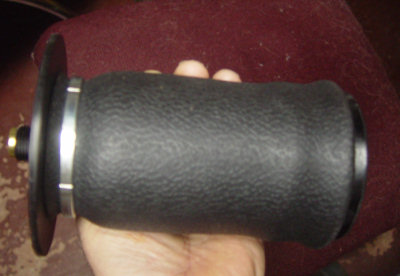
The large batteries need air springs to hold them up. The air springs need compressed air. The spare tire is the air tank.
Since we will then have a larger battery on board, and an air supply, we may as well use it for some more electric goodies.
An Etek powered 5th wheel that will drop down when stopped at a light. This 48v motor will accelerate the car from a stop to nearly 30 mph, using only electric, therefore further saving gas, and allowing pure EV mode, like the Prius.
This blog is the story of the development, and it starts at the bottom of the page.
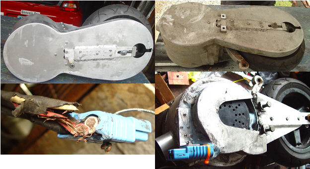
E-Wheel repair and inspection
E-Wheel after one year. original condition on top left
The E-Tek motor story as I understand it. The motor was designed by a DR Lynch, a british engineer. and The Lemco motor company was started to manufacture it. Lemco licensed the motor core design to Briggs and Stratton.(yep the gas engine company.)Briggs redesigned the motor for mass production, and set up the etek motor manufacturing in China.They sold the motor to electric golf cart companies, and electric floor maintenance companies. Their license with Lemco specifically excluded automotive use. When Robot wars became popular, the light weight super torquey motors became the motor of choice for high power to weight fighting robots, and the EV people started looking at the motors as well. EV's based on the motor started to show up. Lemco wanted to be in that market, but was 2 to 3 times the price of the etek. Lemco pulled the license from Briggs, since they could not control where the motors were going.
There was a lot of etec motors in stock throughout the world, and the $350 etek prices started raising as the supply dropped and the demand remained high. I have seen the motors go for $850-$1000. I got mine for $500, and just bought 2 more for that price. There is talk about the Chinese company starting up production again, and also a 3 phase brushless version, but I haven't researched any of that. Anyways I hit a delamination from a truck tire and it grabbed the E-Wheel Anderson power connector, and forced it against the road. By the time I could pull over, the wires had worn through nearly to the breaking point. TheE-Wheel has been under my car for 10 months, including all winter .I used the oppertunity to both fix the connector, and to see how things have held up to the abuse of salt spray and snow. The photo top left shows the enclosure in it's clean freshly installed condition, and then on the right the present dirty case condition. The motor internal enclosure had a lot of carbon from the brushes.
The brushes have worn about 1/4", and still have a lot of material. I would estimate that I have about 250-500 actual E-Wheel powered miles.
The Anderson connector was fine, so I popped out the pins, unsoldered the wires, cut back the wires and re-soldered them to the pins. The temperature wires had also been cut, so I repaired them as well.
The Gates drive belt looked fine.
The tire is now a full slick, the threads having worn completely off.
I made an aluminum bracket to hold the connector so it would not flex, which should prevent the problem from reoccurring.
I will install the wheel tomorrow after the silicone sealant has a chance to cure a bit.
In all, it has held up pretty well.
Been thinking about changing the E-Wheel's 4:1 gear ratio to 2:1 and blasting off with the gas engine, then FAS and drive as an EV at up to 60MPH. Should be an easy change and would open up a lot of interesting possibilities.
(Posted 5/27/2007 by mikey)
Vboost +MIMA, a winning combo for the Insight
It has been a while since I have entered anything interesting in this blog. This story goes back to the Tour de sol, where I met Doug Hartley who was working on his own PHEV conversion for his Prius. I saw Doug again at Altwheels, where we enjoyed a long talk at each of our cars, and a chance meeting on the way home. Doug has designed and is presently in initial test on 10 KW power inverters with full current control, and a wide operating voltage range and an efficiency over 80%. We hope to have one running on his prius and my Insight soon. Photos soon
(Posted 12/19/2006 by mikey)
Portable charging system
portable solar charger
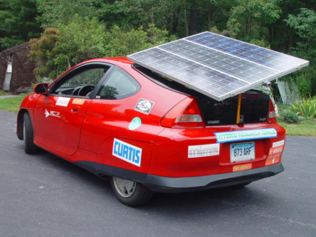
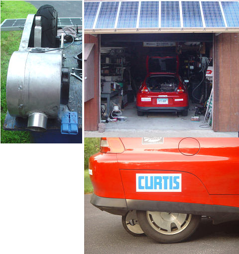
As Altwheels approaches, I keep finding things that I want to add to finish the concept. The latest is a 150W solar charging system that sits on the rear window. It takes about 2 minutes to assemble or disassemble the stand and panels. The idea is to allow the boost system to charge up with solar to give a bit longer range. The array can tilt side to side to capture the sun with a more direct angle to the sun for higher efficiency. The stand could include a tracker if I have time. There goes my passenger seat.
(Posted 9/5/2006 by mikey)
Holy Bat Dropings Robin it is an electric car
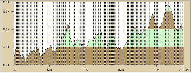
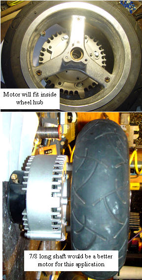
EV Range test route profile
I am so happy. We went to a late movie, and on the return trip, the secondary highway (45mph limited) was pretty much deserted. I had finally put a furnace air filter over the air inlet of the blower, and ran a new wiring tube to the car underside so I could turn on the blower. I started with a 48V charge of about 98%. I got into autostop at a light, put the car in neutral, and clutch out. I put down the 5th wheel with blower running, and took off. I got up to 30 mph pretty quickly, and found that I was cruising at about 28-32, depending on the direction of the grade. The slightest down hill, and the current will drop right down. The surprising part was the hill climbing. On some hills that would normally be a problem, (< 50mpg) in 4th at 30mph; I was cruising right up them with the speed only dropping to 25mph. Remember this is at 175A peak, the motor can take 300A. Now the good part, I watched the motor temp, it was stable at 102F, and I never saw it over 107F even after a 1/2 mile hill. I continued for 23 miles like this, with the FCD at 150mpg, and the l/100klm at 0. I will know the amount of battery charge that it took to do it when the battery has all night to settle out, but it is above 40 %SOC for sure. Maybe a 30-40 mile range on pure electric, with lead acid batteries. HOW COOL IS THAT! I should try a 3:1 ratio, as I bet it would have enough power to go up to 45mph. While I am at it, I should put an encoder on it, and have it spin up to the same speed as the road before the cylinder pushes it down, then you could engage it on the fly, and also have regenerative charging of the 48V pack. The bigger EV only cars, use two Etek motors shaft to shaft, for doubling of the power. Lots of possibilities.
(Posted 8/7/2006 by highwater)
Air cooled 5th wheel
got busy today
I have had the components ready for several days now, but was not happy with any of the blower mounting schemes, as they all required another big hole in the floor.
I finally settled on what could be a good, easy solution.
I took the battery cooling blower from a Prius, and made an adapter to fit a shop vac hose. Made the motor mount have an inlet that fit the shop vac hose, and welded up a cover for the brush area that has an outlet facing backwards. Plumbed it all in after fabricating an angled mounting bracket for the vac hose. I covered the hose with 3" aluminum ducting as a heat shield, where it passes over the exhaust. I used a piece of an air filter from my domestic hot air heating system, as an inlet air filter, and connected the blowers' power wiring to the cabin of the car so that I can turn it on and off.
(Posted 8/5/2006 by highwater)
Breaking away from the grid
I finally got around to putting up some solar panels on the garage to charge up the boost batteries. I was expecting to just run the panels which put out 150v @ 2.9a into the Vicor batmod in place of the rectified 120vac that I have been using from the grid, but found that the dc/dc needs 3.25amps to run, so the current was not sufficient. I rewired the panels so I now get 75v at 5-6a, and can charge directly. Of course that means I will have to come up with a charge controller so I don't cook my AGM batteries if I forget to disconnect them when charged. Always another project to drain my limited time. What would I do if I had a real job???
(Posted 8/1/2006 by highwater)
Cleaning things up for the trek to Madison
Cleaning things up
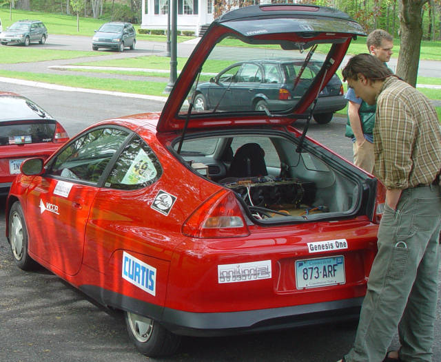
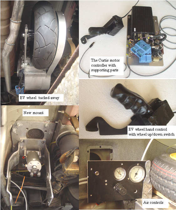
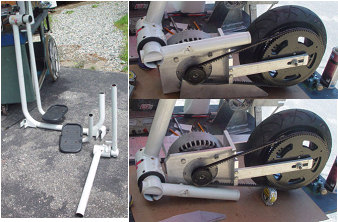
The Curtis controller will control the motor with a minimum of external components, but to be safe, it needs to have a main disconnect relay, a pre-charge resistor, fused control circuits, and safer wiring. I made a contour fitting hand control with a switch, for lifting and lowering the EV wheel via a solenoid valve. The photo shows just how few components are needed for the electronics of a simple EV. I moved the air control stuff to the rear. The exhaust was rerouted to give better clearance under the car. The 5th wheel tucks neatly under there and hardly shows when retracted.
(Posted 7/14/2006 by highwater)
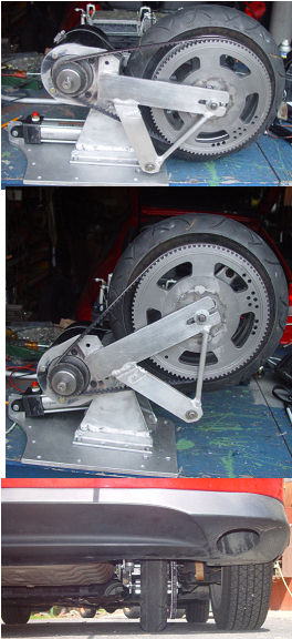
Final 5th wheel
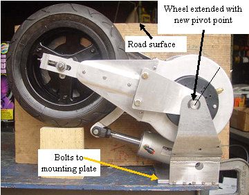
new pivot position
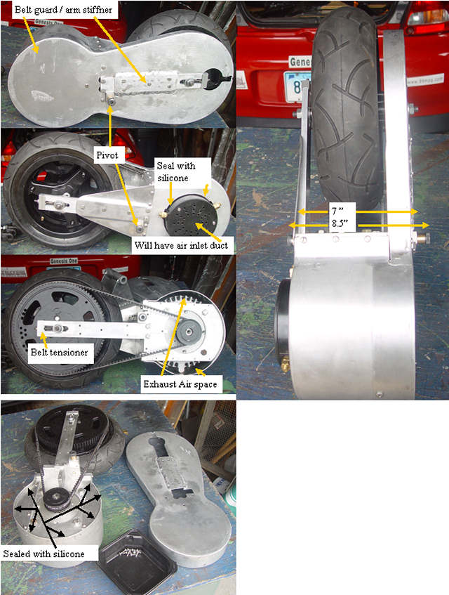
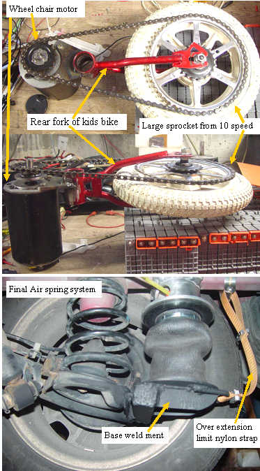
After a lot of careful measurements, I have decided to pivot the 5th wheel right on the central axis of the Etek motor. I made bushings and pivot shafts and was able to attach them to the aluminum main plate. Instead of the two cylinders I found a single 2.5" bore unit that should be able to generate enough down force, and has enough travel. Made the whole unit so it attaches to a single plate. I hope to finish the system and mount it tomorrow. The Etek motor will now be completely sprung weight, and the wheel should follow the road much better than the see saw pivot in the last mount.
WOW that Etek has some power. I started on flat ground, and at set current limit for the controller(177A), I took off smoothly and got to ~ 31MPH before the amps dropped indicating I was at top speed. I did not measure the time, but it was faster than a good hypermiler would take off, about my normal takeoff speed, lots better than the wheel chair motor. The neat electric whine noise level even with the hard mounts throughout, was not very high. I was able to climb small hills with no noticeable speed drop, at about 75A, so once rolling, I could probably have 3:1 ratio, instead of the 4:1 I presently have. The 60PSI in the spare tire/air tank, was able to generate 133 lbs of down force, with my mechanical linkage and 2.5" bore cylinder which lifts the rear of the car about 1/2 inch when down. When up, the wheel is held up with over 100 lbs of force. I only had a short wheel slip when I first took off with the wheel on sand, The tire flattens to about a 3"X 4" patch on the road. I need to move the exhaust a bit to keep things from bumping when on rough roads. The wheel has about 4" of road clearance, and sits about 5-6 " behind the rear wheel track. I went about a mile under electric power, and the motor was not noticeably warm when I returned. In all, I am satisfied that it is in the right power range for the Insight even with the extra weight. I have gathered the components to make it fit my Dodge caravan trailer hitch, I have to try it. I disassembled the whole motor enclosure, washed it with alcohol, then reassembled and sealed with silicone. a MIMA type temp probe was installed right on the motor face plate, and I sealed the case. The temp will be monitored to understand the thermal characteristics, and the current limit will be adjusted accordingly. The motor can take 300A for 1 minute, I am only at 177A. lots of room to play.
Poor batteries, better keep the amps down.
(Posted 7/4/2006 by mikey)
5th wheel part 2
5th Wheel ready for mounting
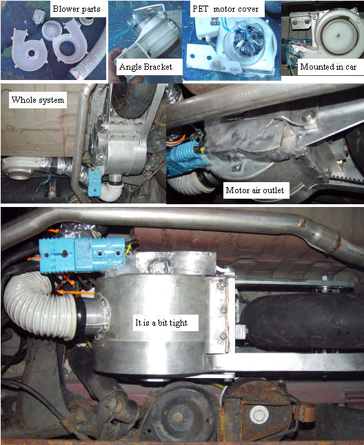
The 5th wheel assembly is ready for mounting. The sealed enclosure shown will have an air outlet added somewhere. The brush area will have an air inlet duct added. This way I can blow forced air through the motor and run it hotter. The pully shaft and motor face will have water proof seals, as well as the shield/air duct area. The pulleys will get wet, and the housing will vent/drain at the bottom. The pivot will be at the bottom so the dual air cylinders can have a long lever arm to get maximum downforce in the limited area available.
(Posted 6/23/2006 by mikey)
Back to the 5th wheel
a possible mounting system
Finally had a nice day to work on the car. Looked though the junk to see what I could find for a strong hinge that I could use to pivot the 5th wheel/motor assembly. I figure that there would be an advantage if we use the weight of the motor to give more down force rather than the see saw design I did on the first assembly. On the other hand, the see saw has the safety advantage of being able to be balanced so that the wheel lifts with gravity if the air fails. The motor needs to be protected from water, dirt, and dust as it is an open frame design. I also need to be able to align the whole assembly with the car. I found an exercize machine that I took from the dump. It was made to hold heavy people so the bearings look strong and tight enough to transmit the motors 160 lbs of push to the car. Got out the pipe cutters and here is what we have.
(Posted 6/11/2006 by mikey)
No assist when warm
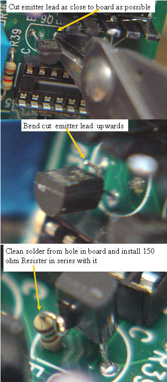
Four of the guys reported that with the hot weather, their MIMA systems were loosing assist. Careful observation by Nemystic, and some testing by Hafnhaf with some freeze spray identified that it was a thermally related issue. I could not duplicate the problem on my test fixture, so I made a mount for the MIMA board where I could access it while driving. Nemystic brought his card down, so I would have one of the bad boards to work with. With a can of freeze spray in hand, I quickly found that Q6 the switching transistor that drives the MAMODE1 20KHZ PWM signal was the thermally sensitive component. The problem was that the MAMODE1 signal showed no measurable change between working and not working. Further testing showed that the gain of the 2N3704 transistor being greater than 100 would cause the assist to stop. Cool the transistor which drops the gain, and it works fine. I pulled out my heathkit semiconductor curve tracer, and was able to clearly see the gain change. I went through all of the transistors in my stock, and found that more than half of them had gain higher than the 100. I selected one of the transistors with a gain of 70, and replaced the part on Nemystics board, and the board became stable with no problems even when baked to 122F in the closed car. To finish the confirmation test, I selected a transistor with the highest gain of over 200, and put it into a new board that was not having the problem, and sure enough, assist stopped working as soon as the temp got to 80F. Now I need to come up with a board patch that will allow any transistor to work reliably. Further testing with the new boards I just built confirmed that this fix works well, so if you have this problem, and want to fix it your self, just cut the emitter lead, bend it up, and after cleaning the hole in the board install the 150 ohm resistor and you should be good to go.If you want me to fix it, send the board back and I will turn it around asap.
(Posted 6/2/2006 by mikey)
Got the exhaust finished
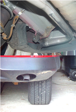
New Exhaust leaves room for 5th wheel
I was concerned with the exhaust outlet being under the car. I went to a local muffler shop that has a pipe bender, and we made a custom pipe to get the exhaust to where it was supposed to come out. Noise: really quiet when the engine load is at say 100-150 MPG, and gets progressively louder as the load goes up (bigger explosions in the pistons) At WOT, it sounds a bit loud. At say 75MPG on the highway you can hear the exhaust over road noise. I like the audible feedback of load, and am begining to learn how to use that with the MPG bargraph as engine load feedback.I have a DB meter somewhere, and I will do some measurements.
(Posted 5/26/2006 by mikey)
Starting to plan the trip to Madison
Route to Madison
Looking a bit into the future, I am starting to prepare for the big trip out to Madison for the Hybrid Festival. I plugged in the start and finish points, and the GPS has picked the route you see above. I am not a fan of long driving odeals, so I would like to take my time and drive 5-6 hours per day max. If anyone along the route would like to get together, contact me, and I will see if we can work it into the trip.
(Posted 5/26/2006 by mikey)
New 5th wheel
The Etec on the 5th wheel, will need a complete new frame. It is possible that the wheel could be mounted directly to the motor, thus making it a wheel motor. it would still have the unsprung weight issues.
(Posted 5/25/2006 by mikey)
One hour of electric priority
Pretty bumpy route
I finally got a chance to go for the gold. I have driven this route over 100 times, the max MPG was 84, going really slow. Typical MPG driving at 35 MPH is about 65-75 MPG. Look what I got tonight, with the GPS trip log to show the distance and average speed. Yea it works. The trip started at the left and ended to the right, so it was an up hill trip.
(Posted 5/25/2006 by mikey)
What is that orange tail on my Insight
Plug it in for higher mileage
I thought that you would enjoy a photo of my car being charged at the hotel. PHEV sticker needed.
(Posted 5/22/2006 by mikey)
Back to the 5th wheel with some power in our pocket
Ok now that I have a respectable motor, I also have an oppertunity to fix all of the issues that the first prototype wheel had, and build something that is ready for a summer and winter of riding under the Insight. That is a big step, lets see how far I get. The Etec specs are pretty impressive.Lots of torque capabilities. Without spending any money or good will, I need to stay with the Curtis controller,it is rated for 275A, and the motor can take 300A, so it is a good match. The controller has built in current limiting, and I will connect my hall effect ammeter before trying this out in the car, so I can closely watch the motor current. The 4:1 reduction that I had chosen with the wheel chair motor is going to give us some serious ft lbs at the road, even with reduced current, so I may need more down force to prevent scrub out. Lots to consider.Allignment is another issue that could use some work. The ideal system would allow turning without side scrub of the 5th wheel which will need to be back of the rear wheel centerline by 4 inches or so. Then there is the high speed option of directly mounting the larger 14" wheel to the motor shaft, or through a 1:1 drive, which would put the top speed up in the 80-90 MPH range if the tire don't blow out at 3000 RPM
(Posted 5/21/2006 by mikey)
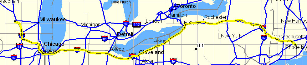
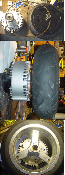
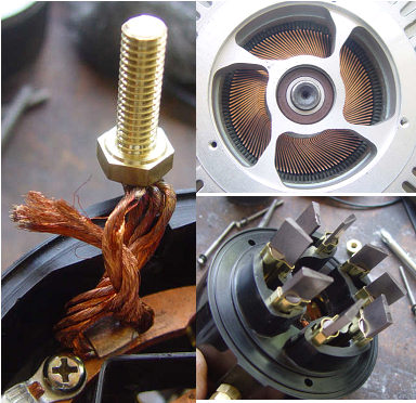
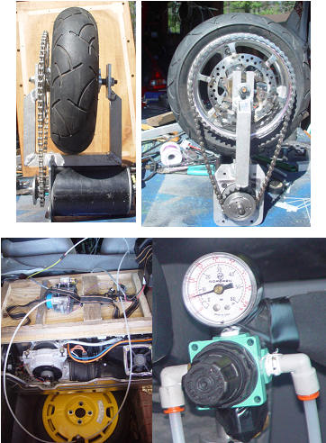
The Etek motor
After having lots of people at the Tour de sol and people at Insight Central as well tell me about the Etek motor I set out to source one, and found that they were in short supply. I went to the MIT swap meet today and scored one. The brush cover came off as soon as I got home,so I could see how it was made.I found that the brush to input terminal wire was not assembled correctly with about 1/4 of the copper strands not connected. I soldered the loose strands to the terminal and will just have to live with it. You can tell that Briggs was set up to bang these motors out. Very inexpensive and clever design.
(Posted 5/21/2006 by mikey)
The EV Wheel
Well it is almost there, I did not provide a way to align the wheel with the car, and I am thinking that that will be pretty important with only a little motor. Still need a battery charger, and with only one day remaining, I will just live with it, no more time for the EV wheel. The gates poly drive is real quiet and smooth, the air cylinder fit pretty well, and since the wheel is on opposite sides of the hinge point, so the weight is nearly neutral, On the lift side, the cylinder is bottomed out, and is held with about 50 lbs of force.On the down side I have about 75 lbs. I will measure it to be sure. On the down stroke, the wheel drops about 2" below the other rear wheels. I don't think it looks bad from the rear either.
(Posted 5/9/2006 by mikey)
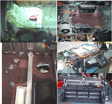
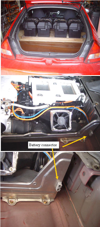
Attachment plate / Ripping the battery pack out .
I have to cut into the car to install a structural atachment 3/8 thick aluminum plate.The 5th wheel assembly will mount to this. To make a strong thread in the plate I pressed full 1/4-20 stainless steel nuts into milled cavities on the back side. The area that is right behind the shock absorber weldment to the frame looked like the best place for it, but the area on top of this is under the battery pack. Pulled out the manual, and after removing the aluminum cross beam behind the seats, 4 bolts, two braces, a bunch of connectors, and it is loose. I grabbed the air inlet and air outlet sides, where there was no metal to touch. The side facing the passenger side of the car has good plastic cover. I figured that the thing had to be field swapable by one guy, so I leaned against the passenger side of the open rear hatch. I grabbed the fan housing with my left hand, and the lifted while my right hand pulled it towards the rear. This got me to the point where the bottom of the pack was resting on the top of the rear wall of the electronics box. I moved to the rear of the car, and again reached the rear with my right hand, and the fan enclosure with the left. I was able to lift it right up so It was comfortable to hold. I easily got it up to my work bench. reversed the process to put it back in.
(Posted 5/9/2006 by mikey)
First full weight test
first fully loaded test run
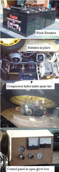
I coulden't wait any longer for the batteries, so I broke the bank and bought some trojan AGM-31's They weigh 75 lbs each. I cut 3/4" plywood for the base to give the batteries a flat surface to rest on. To keep them in place I used pine boards cut to fit between the spare tire well walls and the batteries. I placed wooden wedges to hold everything solid.I finished piping the air lines for the air springs. I placed 1" OD nylon wiring tubes so I can add and remove the airlines and wires easily. One goes under the car, one to the rear of the electronics box, another between the electronics box rear and the rear of the e-brake, and finally one from the rear of the e-brake enclosure and the driver side of the shift console. Now it takes only a minute or two the fish a wire to the front. The car needs 18 PSI to support the batteries to the normal suspension height. The ride was really smooth, with hardly any heavy feel. The springs work well.
John Snook, MIMA # 019K has sent a check covering the cost of the batteries . Thank you John, I can buy an Etek motor for the 5th wheel so we get better pickup.
(Posted 4/30/2006 by mikey)
Test runs and 5th wheel
Air system test and 5th wheelV2
I got a chance to do some driving with the air springs, and notice a few things. You need to keep at least 5-7 psi in the bags to inflate them so they move without damage. The min recomended is ~ 20 psi. At 6 PSI, the car rear is lifted about an inch more than without the spring. Conclusion. Unless you are carring weight, it would be better to take the springs off. Unless you like the feeling of going down hill all the time. I put two batteries and the spare in back to see how it would ride. The ride was smoother as one would expect with more mass. Even with two 61 LB batteries the springs only needed 8 PSI to get the height about normal. I worked more on the 5th wheel and it's attachment to the car. I had a policy of not modifing the car so much that I could not return it to normal, so I may as well go the whole way here. I was originally thinking of connecting the motor/wheel assembly to the torsion bar that the two rear wheels are mounted to, by clamping on. I am not happy with the positiveness of that for something that could be hit by a piece of truck tire or frozen slush. The new improved plan will make an aluminum sub structure that connects to the sprung chassis, and clears the torsion arm and wheel support arms. It will be bolted through the bottom of the car so that it is made part of the structure. The air cylinder/5th wheel will attach to this sub structure. It will be made strong, over built. I am not going to use chain for the drive, I will use a super strong gates cogged belt drive. The same thing the new Harley motorcycles are using. Hope to get Gates to give me the drive components. Curtis sponsored me with a 1204 36-48V 275A PWM controller, and two big decals for the car. Vicor is also going to give me the BatMod constant current power supplies that I will need to regen back into the 48V battery if the oppertunity presents it self.
(Posted 4/27/2006 by mikey)
Better wheel
a stronger wheel
I drilled a 1" hole in the space between the seat back and the HV cable exit hole, that will allow airlines and EV control wires to be brought into the car. I assembled a quick air spring air supply with a regulator and gauge.Seven PSI fills the springs and provides a slight lift. I believe the air springs provided a noticeable quieting road noise, but the real test will come on the first run with a full compliment of batteries. I went to a bike shop today looking for a better wheel, and a new chain. The sprocket attachment to the kid's bike wheel is a bit too weak to take the stress of accelerating the car (my intuition). The bike shop was no help, as the large sprockets are made for the crank, not the rear wheel, and the rear wheels were all to big in diameter. The 12 inch wheels are all cheaply made. In the way home I passed a small garage that sells scooters, so I stopped in. The guy had some junkers in the back of the shop, and let me have the two wheels from an old french scooter. I was able to weld the large bike sprocket onto the brake plate of the scooter wheel. This is a wheel that is big enough for the job, the weak link being the welded sprocket, but it is still much stronger than the bike wheel. Now I need to make a new fork for the wider wheel.
(Posted 4/24/2006 by mikey)
Air spring and EV wheel begin to take shape
Todays progress
I finished the air springs system, by adding the over travel limiting nylon straps. Still need to build the pneumatic system. I am going to use the spare tire as the air tank, with a little 12V compressorwith automatic air pressure switch. Where to bring the air lines and EV wires into the cabin is the next task. I played with the EV wheel setup a bit, and if I get a good chain, I should be able to do a rough test of the system to see if the wheel/sprocket system is strong enough.
(Posted 4/23/2006 by mikey)
The ideal battery for a 200 mile commute
A tip from an Insight fan led me to call the Kokam battery company. http://www.kokam.com/english/product/battery_main.html I got to speak with two of the owners, they seem like a nice small company, with a great product. I will be discussing the project with them over the next few days, to see if we can find a way to get some of those cells in my Insight. 18 200AH cells would do it, or 180 20 AH cells. No response from them, so It looks like I am back to Lead Acid. Bummer!
(Posted 4/17/2006 by mikey)
First power up of boost power supply
Exploding batteries and the boost power supply
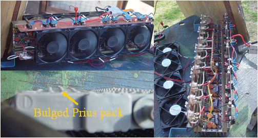
I finally got the controll board working, and the fans and mounting base made and tested. The first full power run was disapointing, and resulted in one of the prius batteries almost exploding. I switched to the tired 12 V trojans, and got a good 20-30 minutes of playing. The load I used was the same plastic oven as the other power test but the nichrome ribbon had broken. Not very safe. The 10 diodes are each dropping nearly a volt each, which seems to be limiting the maximum voltage. More experiments needed, but the circuits are working. I got up to 13A and 145V.
(Posted 4/15/2006 by mikey)
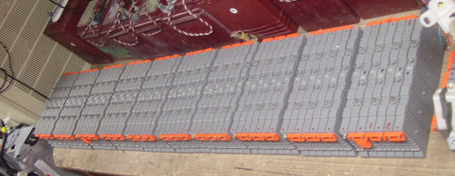
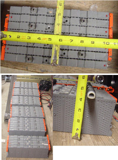
More Prius batteries
Some serious power 500V 6.5AH
Thanks to Craig Van Battenburg,I now have enough prius subpacks to make 10 packs of 7 subpacks. The 50V packs can each power one dc/dc converter. the total 48V capacity will therefore be 6.5AH *10, or 65AH of capacity. If I derate the capacity to the 4AH, that gives me a bit less than 1 hour of run time. Each pack of 7 subpacks weighs about 16.5 lbs, for a total of 165 lbs.The converters only draw 5-6A, so I expect that I may actually get more run time at the lower discharge rate. Now the question is should I also have the 4 lead acids? The prius packs are small, and can be tucked here and there, but I still need to be concerned about cooling them especially when charging. If I can regen to the prius batteries, I would not need to try and stuff more AH into the car, and things may actually be light enough so that I dont need the air springs? I need to come up with a pack monitoring system, even if it is crude to warn of a depleted cell in a subpack Lots of questions need to be answered before this can be sorted out.
(Posted 4/14/2006 by mikey)
Air springs arrive
This Is supposed to hold up the car and 200 lbs of batteries????
I finally got the air springs. They look pretty flimsy compared to a steel coil spring, but I am assured by the Air Lift guys that each can support 850 lbs. The big task with mounting them is the dropping of the rear wheel assembly, and modifing the top and bottom spring mount so that they attach properly. If I ever want to go back to springs, I need to make the changed reversable. I also need to weld on some beefy steel tube to mount the bump stops on, and also make a bump pad for the new bumper position to bump into. The frame extrusion is not strong enough.Major surgery to say the least. I decided that it will be easier to put the air springs on the new bracket, and let the steel springs support the cars regular weight. That way the system will have built in redundancy.
(Posted 4/14/2006 by mikey)
Finishing up the boost power supply
The basic supply with diodes,fuses, and terminals
I got the diodes and capacitors that I needed, and have wired up the unit with fuses, and the output diodes. I want to do a bit more reading on the output capacitors before I power up for the first time. I still need to build the current control system, and have included the 0.005 ohm 1% current sense resistors in the initial wiring.
(Posted 4/7/2006 by mikey)
Beefing up the rear suspension to handle the extra battery weight
The batteries, no matter what type we end up with will force us to give the springs some help. As one would expect in an 1800 lb car with only 360LB of carrying capacity. The 4 optimas are nearly 250 additional lbs, and would likely fit right in the spare tire well, so all the weight would be supported by the rear springs. I like the air spring concept, but it is not clear yet if we could fit one in the spring space. Heavier springs are another option, but we would have to have the rear fitted with all the batteries to be able to spec the required additional weight capacity.I picked up two of the air springs, and will try my luck at installing them over the weekend. As the photo shows, the air springs are a bit on the big side. The springs are loaded with 150lbs in the right hand photo that shows the air spring.
(Posted 3/31/2006 by mikey)
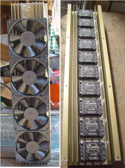
DC/DC mounting and cooling
I was lucky enough to find a compatible heat sink for the dc/dc modules. It took some machining to get things to fit, but this should be large enough with the fans to keep them in the temp zone that they like.The fans can be speed controlled if desired to keep the noise down. The dc/dc converters will need some high current isolation diodes and bypas capacitors that I did not have in my parts bins, so I will not be able to finish the assembly until next week.
(Posted 3/31/2006 by mikey)
Some booster battery options
Prius subpacks in 50V modules could run the converters for about 45-60 minutes continously. but will need BCM type monitoring and control. The ultamate battery solution for the Insight would be a light weight 144V pack of Lithium or other high power to weight batteries, with 20+ usable AH capacity.Like many things in live the good stuff cost too much.
(Posted 3/31/2006 by mikey)
Second boost test run
I got brave again today, and ran a second solo test run. The boost system with only two 12V batteries, the 2500W dc/ac inverter, and the variac and step up transformer could only supply 5-6A, but even that small amount of constant charge made a decent extension of the battery charge. I started the test in Worcester as I got on I 395 heading south. I kept up with the traffic at 65-70 MPH, and got 104MPG for the 22 mile run, and still had 4-5 bars of charge left. No IMA codes, and assist and charge worked normally as well as the SOC meter. All good signs. I get home, and on my front step is a package with all of the DC/Dc converters for the real system, so I can get right to work on it. I may have this ready for the tour de sol after all.
(Posted 3/27/2006 by mikey)
IMA Battery Booster/Balencer/Charge controller.
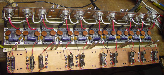
Why do Insights get SOC recalibrations? One cell out of the 120 cells in the pack reaches the point where the voltage starts to drop, and before the cell reverse charges and gets ruined, the IMA turns off assist, and force charges the pack to save it.This is a low capacity recalibration. The one cell that has less capacity than the other 119 cells,rules the minimim end of the discharge curve, even though the rest of the cells could have a lot of juice left in them. A perfect pack only has 4 useable AH of capacity, a weak cell at half capacity would reduce the pack useable energy to 2 ah. I have a new idea on how to do the booster pack. instead of using 5 parallel 48V to 170V 3A dc/dc converters for charging, as I had originally planned, I will now use 10 - 48V to 16V 16.5A dc/dc converters. These are standard half brick power supplies that can do constant current mode with a small current shunt and auxiliary circuit. The supplies are fully isolated so that the inputs can be in parallel while the output is in series. A small Microprocessor based voltage/temp/SOC measuring circuit will control each of these supplies. Every two subpacks will be cared for by this type system, 10 in all. Each BCM node will be connected to a master BCM via an optically isolated serial buss. The master will decide if one of the packs is dropping low, and will instruct that microprocessor to charge longer. The modules cannot be turned on an off very fast, so the charge may be full on for 10 seconds, and off for 10 to give 50% average charge. A weak subpack may get full charge 100% of the time to boost it back up relitive to the others, avoiding the recal. The center tap between the two 6 cell parts of the sub system could also be monitored, and the charge could be shunted to either or both of the subpack . The whole pack could be charged at up to 2500W with all the supplies on at once, therefore allowing a higher use of the electric side of the hybrid.Increasing MPG to hopefully >100MPG. The ability to provide 16A at 144V from the 48V booster pack, allows a constant application of the electric drive at low power. If the main pack is allowed to charge right up to near full, and the boost is turned off, you are back to the stock MIMA equipped Insight. When the big 48V battery dies, you loose active subpack balancing, and are back again to the standard MIMA equipped Insight, but are 250 LBS heaver. Then we add the EV only mode, but thats after we get this battery stuff ironed out.
(Posted 3/24/2006 by mikey)
Booster Battery progress
I have made a mounting system for the 4 deep cycle batteries.I made a plywood base that is the same shape as the rug, so it fits snuggly on top of the electronics box.This assembly will be held down by nylon straps. The plywood will distribute the weight on the electronics box, and the position near the midpoint of the car should distribute the weight more evenly over the front and rear wheels than placing them in the spare tire well(would not fit there anyways). The big surprise was that when looking out the rear view mirror, I can't even see the batteries, and have the full view out rear. I mounted a 50A 600V connector in the lower passenger side of the electronics box, to allow easy connection to the car. As presently wired, the boost current will pass through the MPI current sensor as well as the battery SOC current sensor, and will only charge when the car is turned on. This is where I connected the other day for the first test run, so I will explore the cars reaction to boost charge via this path before moving the connection to the other side of the MPI current sensor. Next will be to get the boost equipment mounted for more testing. I was able to completely charge the 4 batteries with my PV panels during a single day of full sun.
Opps! The extra weight has dropped my rear suspension to within 1/2 inch of bottomed out, without me in the car. Afraid to drive it that way. Will need to look into beefing up the suspension.
(Posted 3/19/2006 by mikey)
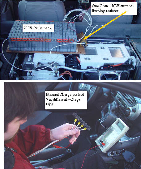
Booster pack test 1
One of the biggest questions about the booster battery concept is weither the car will set an IMA code when it detects a charge that it did not expect. I needed to see what would happen without spending any more time or money on the concept. I built up a 200V pack of the Prius batteries, and charged them up. I tapped off of the pack at the last 4 subpacks, so I had 200V,192,185,178 V. My Nephew Troy was the battery charge controller with an alligator clip and a terminal strip. The current was limited and monitored by passing it through a precision 1% 1 Ohm 150W resistor, and measuring the voltage drop across it.I tied in right at the top terminals so the current passed through the MPI and Battery current meters. The car in neutral at idle accepted and displayed the booster charge which I was able to get to 15A. Next I started to drive, and applied the boost. That also went well, with no issues. I drove for quite a while, then I came to a stop, and still had the charge running, and the IMA light came on, and the check engine light as well. I turned off the charge, and then reset the IMA, and all codes cleared, but the car started with the 12V starter. I drove a bit more, and noticed that the IMA worked normally with the exception that it did not do the constant background charge that would have been expected at the 1/4 SOC point that I was at. MIMA could charge or assist at will, and normal IMA assist and regen during deceleration worked. I let the battery drain down, figuring that at some point the background charge would start, and as expected it did, but only when down to 3 bars. I turned off the engine at the next light, and it started with the IMA system, and everything is back to normal. I need to run some better controlled test,to identify the conditions that cause problems. I was able to maintain 130MPG for several miles without depleting the main battery. It does work, just need to rag out the details.
(Posted 3/6/2006 by mikey)
MIMA logo?
Fenrir has proposed this MIMA logo. It is a nice start,I like it, any comments, ideas, other logos?
(Posted 3/3/2006 by mikey)
FAS
Plug in FAS system
A cool modification to the Insight started with Calpod coming up with up with a simple way to fool the system into stopping the engine in a safe way to simulate the cars autostop feature.FAS This system allows the driver to kill the engine without needing to turn off the key. Highwater came up with a way to latch in the condition using relays instead of a switch so the clutch will not need to be held. This allowed the system to maintain engine off without holding the clutch in. I drew up a simple schematic that will do the job using either a Momentary switch, or the MIMA AR2 output. I added an additional set of wires, that tie into the dc/dc converter, which allows the 12V charging system to run when the engine is in FAS. I now offer the built plug in FAS system as an option for MIMA which has the necessary wiring in the harness. MIMA is not necessary for using FAS. Schematic on the downloads page.
This modification cuts the power to the fuel injectors, which causes the engine to stop. The car must be in neutral for it to remain stopped. Once the engine is stopped, it will restart under the same conditions as the factory autostop. 1. If the brake vacuume is depleted by several brake activations,the engine will start. 2. Step on the gas, even in neutral, and the engine starts. 3. Put the car back in gear, and the car will restart. Each down hill presents you with a decision, should you be charging the pack back up with MIMA, or coasting in neutral engine off getting 150MPG.