|
MCM connections
|
 | |
|
MCM connections
|
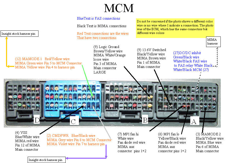
The MCM photo was actually a photo of the ECM connector which happen to be identical. There is a different color code used on the pins of each so don't look at the color on the drawing, it is not valid, just read the words. You will notice that the descriptions are color coded to distinguish the types of connections.
The BLUE text connections are the two ends of the DC/DC converter enable line that goes to the FAS relay.
The ECM end of the harness is plugged into it self to jumper the DC/DC enable line, for normal stock behavior without the FAS system.
The red text is the two main MIMA control lines into the MCM. Here the naming convention varies a bit.
(12) MAMODE1 Red/Yellow is the same as the other pins.
MIMA Green wire Pin 5 to MCM connector: This means that this green wire and it's terminating connector will plug into the connector in place of the stock pin that was in the pin 12 position.
MIMA Green wire pin 5: This will be a bare female pin with short white wire that connects to the fine green ribbon wire.
MIMA Yellow wire Pin 4 to harness pin: This is a male pin with clear insulation over it and will plug into the cars stock harness pin that used to go to pin 12. The insulation keeps the pins electrically insulated. This yellow wire runs to the main MIMA connector and connects to pin 4.
Download and print the high res PDF.
Download MCM PDF
|
|
|
