The end of the Plug and Play MIMA, and MIMA2
MIMA introduction
MIMA Operation
MIMA Users Page
Installing MIMA with The Plug and Play harness
FAQ
Installing MIMA with the pin replacement harness
software
The MIMA Joystick
The MIMA Display
The FAS system
DIY MIMA L
Cable impedance problem with last MIMA systems.
Learning to drive with MIMA
Hardwired Harness
Level 1 Installation
2. Disassembly
3. Thread the Harness
4. Threading the Harness, Cont'
5. Opening the Harness
6. Level 1 Install (rear connections)
7. Fan Diodes Install
8. Battery Amp Monitor Rear Connections
9. Mounting the MIMA system in the car.
10. Level One wiring test.
11. Level 1 Check first power up
Other connections
Main Controller test points
Test 13.6V supply
Test 5V
+ - 12V supply test
Board operational check
12. The first MIMA operational test
13. Testing the fan control wiring
14. Confirming temp probe and fan control operation
Level 2 install
Theory of Operation

Other connections

Other connections
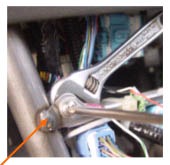
Connect the white wire from the shift console end of the harness to the cars metal chassis, to complete the grounding of the power /fan control circuit.

Everything should now be connected,except the ECM wires, and the MIMA bypass connector. We are ready for the power up test. Whenever powering up a board or system for the first time, the most important thing to watch for is shorted power supplies. This is especially true with MIMA as we use the +12V and 12V from the battery sensor to power our opto coupler input. The rest of the system runs off of the 13.6V main power that has been regulated to 5V. Most modern power supplies can take a shorted condition for a short time without permanent damage, so we will quickly confirm the main 5V power supply first, then turn off the system, reconnect our probes to the +12V and 12V and turn the system back on again to confirm those power supplies.