The end of the Plug and Play MIMA, and MIMA2
MIMA introduction
MIMA Operation
MIMA Users Page
Installing MIMA with The Plug and Play harness
FAQ
Installing MIMA with the pin replacement harness
software
The MIMA Joystick
The MIMA Display
The FAS system
DIY MIMA L
Cable impedance problem with last MIMA systems.
Learning to drive with MIMA
Hardwired Harness
Level 1 Installation
2. Disassembly
3. Thread the Harness
4. Threading the Harness, Cont'
5. Opening the Harness
6. Level 1 Install (rear connections)
7. Fan Diodes Install
8. Battery Amp Monitor Rear Connections
Black pin 10 to Blue/Red ISDC+ 12V BCM A-3 (Tap)
Brown Pin 11 to Light Green ISDC- 12V BCM A-16 (TAP)
White Pin 9 to Red/White ISOC BCM A-4 (TAP)
9. Mounting the MIMA system in the car.
10. Level One wiring test.
11. Level 1 Check first power up
12. The first MIMA operational test
13. Testing the fan control wiring
14. Confirming temp probe and fan control operation
Level 2 install
Theory of Operation

8. Battery Amp Monitor Rear Connections

These final connections complete the wiring to the rear harness. The two temperature probes will be placed into their proper positions once the testing part of this installation is finished. Plug all of the BCM and MCM connectors back into their proper sockets. The wire harness will have the covers reassembled once we have confirmed proper operation and correct wiring in the next steps.
8. Battery Amp Monitor Rear Connections
Connector refrence for the three connections

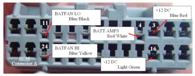
Black pin 10 to Blue/Red ISDC+ 12V BCM A-3 (Tap)
This Black ribbon wire connects to the Blue/Red wire from the BCM A-3 connector.

This is the +12V reference supply from the battery current sensor. STST the connection.
Brown Pin 11 to Light Green ISDC- 12V BCM A-16 (TAP)
This Brown wire fron the ribbon connects to the Light Green wire from the BCM A-16


This is the -12V reference supply from the battery current sensor. STST the connection.
White Pin 9 to Red/White ISOC BCM A-4 (TAP)
This White wire from the ribbon connects to the Red /White wire from the BCM A-4.

This is the amp signal from the battery current sensor. STST the connection.
Level 1 Installation:
2. Disassembly
3. Thread the Harness
4. Threading the Harness, Cont'
5. Opening the Harness
6. Level 1 Install (rear connections)
7. Fan Diodes Install
8. Battery Amp Monitor Rear Connections
9. Mounting the MIMA system in the car.
10. Level One wiring test.
11. Level 1 Check first power up
12. The first MIMA operational test
13. Testing the fan control wiring
14. Confirming temp probe and fan control operation