|
The real pulses
|
 | |
|
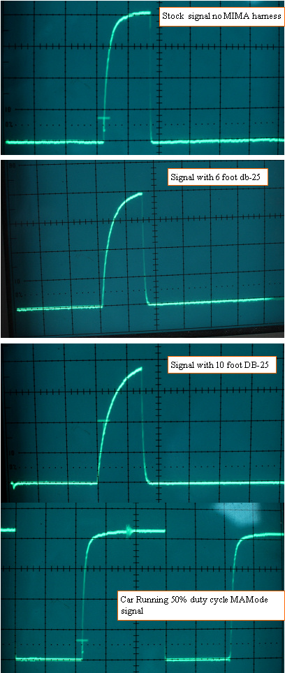
comparison of pulses
|
I went back out to the car armed with the storage scope, the MIMA kit from Trevor in AZ, and a 6 foot DB25 cable that I found in my cable stock.
Be aware that the short pulses are present only during the period where the car is booted up, but the car is not running, and I believe that this is where the car checks for reliable communication between the modules.
Once the engine is running, the pulse width gets to 20 KHZ 50% duty cycle.
Started by lifting one side of the resistor and used the 10 foot cable that was so bad the other day that the car would not even start.
The idea was to work up to the best pull up resistor value by putting a 20K pot in series with the added 1K and adjusting the pot while watching the signals and the cars behavior to determine where the system starts to work.
First step was no resistor at all, so I expected the same erratic try at starting the car and erratic MIMA behavior, once the problem was seen, I was going to reconnect the pull up resistor through the pot to see where things settled down.
I took a 20 mile run and the car started normally, and ran fine with autostop and MIMA all working normally????? whats going on here?
This is exactly the same setup and components that did not work at all the other day???
I snapped some photos of the signals. The stock signal just barely makes it to 4V, not to 5 as I had assumed should be the correct level.
The 10 foot cable showed the slowest rise time and lower max voltage as expected, and the 6 foot cable looked pretty similar in max V, but slightly slower rise time to the stock signal.
The car never acted up at all, but both Spence and Tim seemed to feel that problems got noticeable once things got warmed up.
I figure that the next test must be with the car interior as warm as I can get it. We are supposed to get some sun tomorrow,with temps near 60, so I may part it in the direct sun, and add some BTU's from my electric heater, and repeat todays test to see if anything changes????
Bottom line, if you have not installed the system best hold off until we can pin this down.If you have installed the resistor and see improvement, you may want to raise the value to more like 2-3K.
As soon as I get the new 6 foot cables I will compare the cables for effect on the pulses.
I did get to tweak the pot a bit and found that the pulse with 10 foot cable was able to be pulled to the same 4V as the stock signal with ~4K pull up.
Had to go down to ~ 1.5K to get the pulse to square off at the top like the stock signal, but an starting to think that the MAX volts reached is more important than the fast rise time?
Will report what I see tomorrow after more testing.
The first systems had no issues like this, and I know we used 6 and 10 foot cables, so we again have a mystery.
Hard to fix something that is working, so I have to get back to where it does not work to get any answer.
Note that the pulses on the top 3 traces were 5uS/DIV, and the bottom was 10uS/DIV, all are 1V /division on the voltage scale
|
|
|
