|
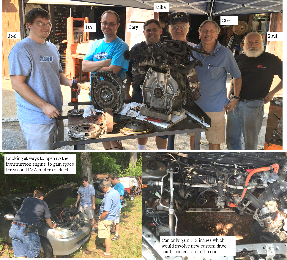
IMA-EV mod workshop 1 discussing the options
|
 | |
|
IMA EV workshop 1 the team
|
The options discussed for the mod covered a of of things so I will try to filter it down based on the final consensus
A stub axle firmly attached to the motor output flange would be the best place to start, so we will make the shaft as soon as a bearing is selected.
the IMA rotor will be bored through to eliminate the bolt attachment rear surface.
Bearings that can stand a 400 lb side load (clutch) and allow maximum free space will be sourced to fit inside the IMA rotor.
Once this is made we will test it on the engine I have on the bench, or the Insight on a test stand.
A scaled drawing of all the components will be made including the bearings.
The pin clutch is still the best plan although we have no idea what that will look like until we see how much space we have to work in.
Some concepts to consider
Smart EV clutch:
This would not allow the EV clutch to activate or deactivate unless the IMA is stopped and the engine is stopped (clutch in engine stopped)
Concept:
A magnet or several magnets would be inserted in the stub axle.
A coil on the rotating rotor would generate pulses whenever the rotor and the stub axle/engine were not linked, as in the EV mode.
Pulses would be rectified and would charge a supercap for energy storage to generate a regulated DC supply within the IMA rotor clutch assembly.
A surface mount PIC micro would be the smart clutch processor.
The pulses would also tell the micro if the stub axle is turning at a different speed than the rotor (pulses). an optical or serial signal would be need to communicate to the smart clutch the users intention.
Not clear as to the best way to accomplish that communication.
The clutch pin actuator (small gear motor or solenoid), would push the spring loaded pin / pins toward the clutch plate and the IMA motor would be rotated slowly until the pins engaged.
The main clutch is out so IMA would be commanded to rotate slowly until the pins were engaged in the stopped engine side of the clutch.An engaged/disengaged control signal would be sent out from the clutch to confirm it is ok to start the engine.
Going in to EV mode on the fly.
Main clutch in, fas to engine off, send EV disengage command.
When flywheel stops (dynamic breaking with IMA motor)and shows no relative rotation to the stopped engine the smart EV clutch would pull the pins out and confirm it is disengaged and you would drive in EV mode which could allow MIMA or possibally the TPS signal (throttle pedal)to control the IMA motor in the EV mode.
Starting the car:
Main clutch in, engage command sent, EV pins out, rotate IMA slowly until springs engage. send engaged signal,
start engine normally with IMA.
going from EV to driven on the fly:
main clutch in,send engage signal,wait for stop, pins out,slow rotate, engage complete start engine or pop clutch to restart.
If this don't work plan B:
Second IMA motor driving one or both of the rear wheels with timing belt drive.
several ways to make it happen no plans yet.
Ima motor and transmission would not be mechanically modified, but the three proximity position sensor signals and the 3 phase drive signals would be switched to the second IMA motor and the car put in neutral engine off.
Drive via MIMA like control or switch scaled TPS signal.
that it for today
|
|
|
